Product Family Datasheet
Three-Side Emitting LED Neon Flex · 1 model
Preview specifications and dimensions for this product family. The PDF opens in a new tab; download from the preview.
Preview Datasheet
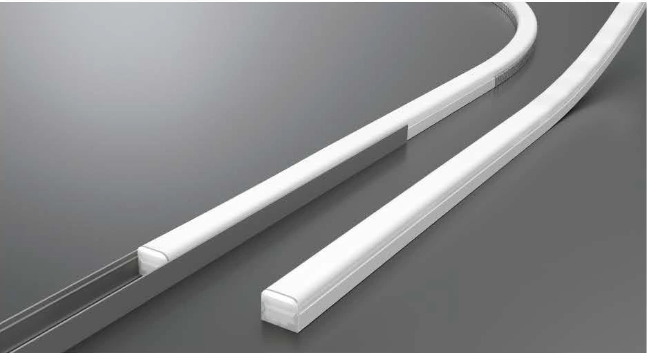
Original model-specific catalogue images. Dimensions in mm; hover or tap a view, then select the main image to enlarge.
Architectural LED Neon Flex
NF03025R · a 30 × 25 mm multi-face luminous profile
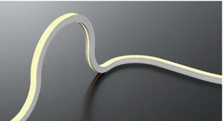
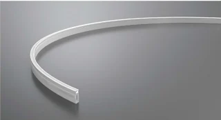
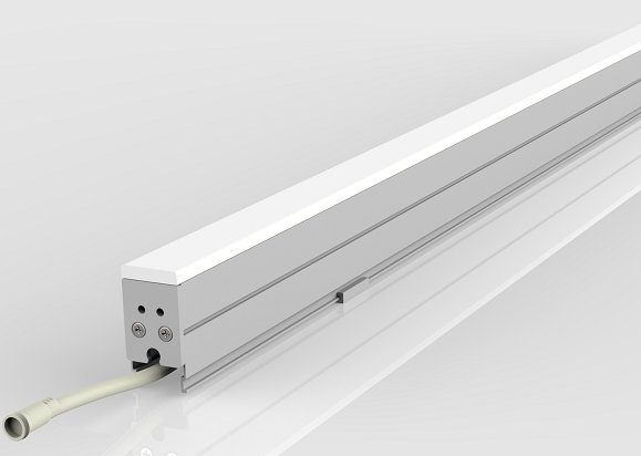
NF03025R uses a three-side emitting profile for architectural details where the illuminated surface remains visible from more than one side. Review the original product view and rounded 30 × 25 mm section before planning an exposed line of light.
Features & Specifications
Profile dimensions and bending data for NF03025R are shown below.
NF03025R has an illuminated top and two illuminated sides within a rounded profile. The three emitting faces suit details where the line remains visible from more than one direction.
Its 30 × 25 mm section needs a mounting position that leaves the intended faces exposed. A recess or channel may conceal part of the light-emitting surface.
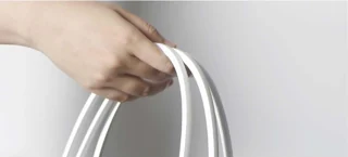
The listed minimum bend radius and cutting interval govern the route. Plan the curve and feed position around those model-specific limits.
Light Configuration
Explore White, Duo, RGB and RGBW options for NF03025R. Compare the illustrated appearance for architectural outlines with top and side emission. The listed beam angle is fixed at 120°.
Drag to rotate · Scroll to zoom · Based on profile dimensions
LIGHT CONFIGURATION
Select a light configuration, then explore its colour or CCT options for the model shown.
Three-side emission.
NF03025R profile.
White uses a fixed CCT; Duo offers 2700 / 6500 K dual white. RGB provides colour effects, while RGBW adds a white channel.
Illustrative LED neon flex colour preview. Screen appearance may differ from the finished product; this preview does not represent measured light distribution or illuminance.
Project References
Architectural outline-lighting application references, not verified installations of this product group.
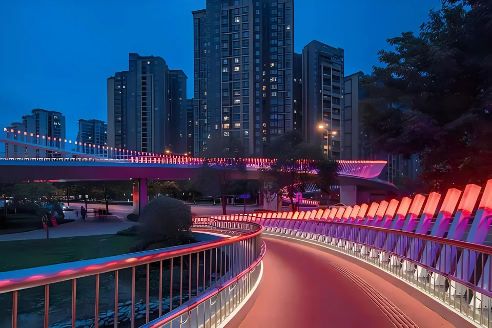
Continuous illuminated edges and railing accents follow the curved pedestrian route.
View Project →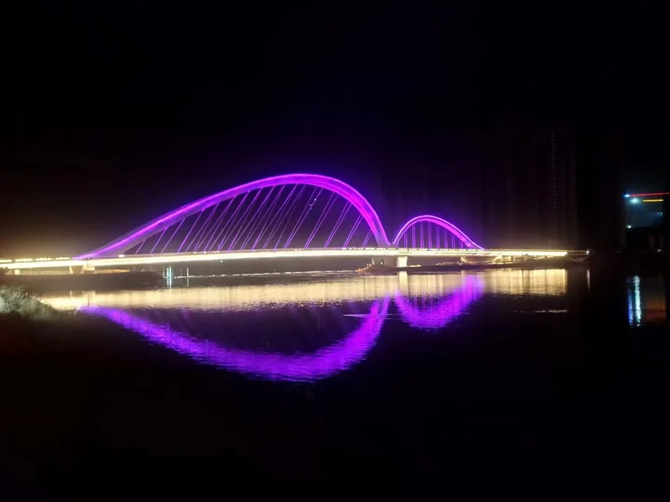
Continuous deck-edge lighting gives the illuminated bridge a clear horizontal outline.
View Project →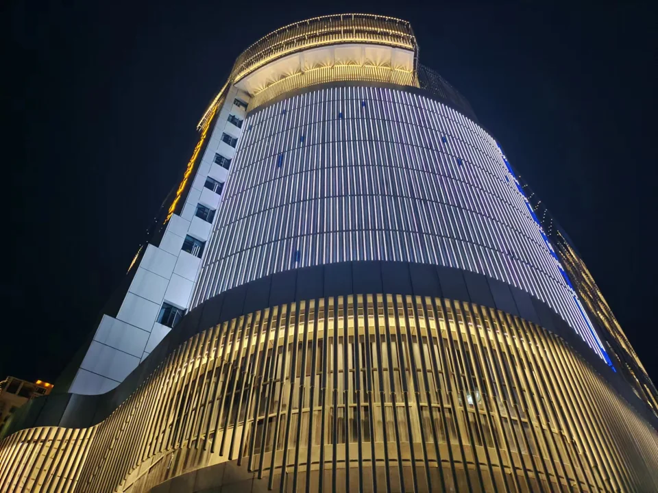
Linear accents mark the theatre’s upper edges alongside the patterned curved facade.
View Project →Technical Documents
Product specifications and technical files for your lighting project.
Three-Side Emitting LED Neon Flex · 1 model
Preview specifications and dimensions for this product family. The PDF opens in a new tab; download from the preview.
Preview DatasheetProject-specific documentation
IES / LDT photometric files, installation guidance and CAD drawings can be requested from our product selection team.
Request Technical FilesBrowse available certificates and check the product and model scope in each document.
Related Series
Compare a different bending plane or emitting profile for the next architectural detail.
Related Products
Compare rigid linear profiles, narrow wall washers and round pixel lights for other details in the same lighting project.
FAQ
Model selection, bending, cable routing and installation planning.
It describes the luminous faces of the profile shown in the original catalogue image. It does not establish a measured viewing angle or independently controllable light sources on each side.
White, Duo (2700 / 6500 K), RGB and RGBW are available in the light configuration selector. White and Duo are listed at 25 W/m. Confirm the configuration-specific power and light-output values for RGB or RGBW before sizing the power supply.
Its minimum bending radius is R500 mm. Use the original bending diagram and maintain the required radius; do not infer a smaller radius from the product photograph.
Yes. The visible result depends on how the mounting detail covers the emitting surfaces. Review the 30 × 25 mm profile and the selected channel together if side visibility is important.
No such use is established by the supplied product information. This page lists IP65, not a submersible or vehicle-load specification. Review the actual installation conditions before ordering.
The listed beam angle for NF03025R is fixed at 120°. Three-side emitting describes the luminous surfaces of the profile, not an adjustable optical setting. Changing the preview colour does not change the listed beam angle.
The preview illustrates the product appearance and light colour. It does not show measured light distribution or project illuminance, and screen colour may differ from the finished product. Use it for initial selection and confirm the required lighting performance for your project.
Controller and wiring requirements depend on the selected White, Duo, RGB or RGBW version. Share the model, configuration, run length and intended control system so the compatible driver or decoder can be confirmed.
Project Support
Share the installation drawing, profile space and light requirements. Include the route lengths and proposed feed locations so the model and configuration can be reviewed together.
SELECTED MODEL: NF03025R
No light configuration selected