High-rise facade lighting works best when linear fixtures follow selected architectural features and their positions are coordinated with viewing angles, facade joints, power distribution and maintenance access. Decide first whether people should see a luminous line or an illuminated building surface. These effects need different optical evidence and placement checks, even when both use long, narrow fixtures.
Develop the elevation and mounting sections together. A continuous line on a concept drawing does not establish a buildable lighting run, and a fixture that fits within a recess may still be visible from occupied rooms or impossible to replace.
Decide what the linear lighting should make visible
“Linear” describes a form, not a single lighting effect. Establish the intended result before comparing profiles or calculating quantities.
| Intended result | What the viewer sees | Evidence needed for selection |
|---|---|---|
| Direct-view outline or luminous band | The emitting face of the fixture | Appearance from relevant angles, emitting length, end effects and performance at the intended operating level |
| Light on an opaque fin, band or wall | Light reflected from the building surface | Configuration-specific photometry, target geometry, material properties and a representative mock-up |
| A combination of both | A luminous line beside an illuminated surface | Separate acceptance criteria for source appearance and surface illumination |
A nominal beam angle does not establish that an architectural linear light will wash a wall evenly. Conversely, a fixture designed to illuminate a surface may expose bright individual sources when viewed directly.
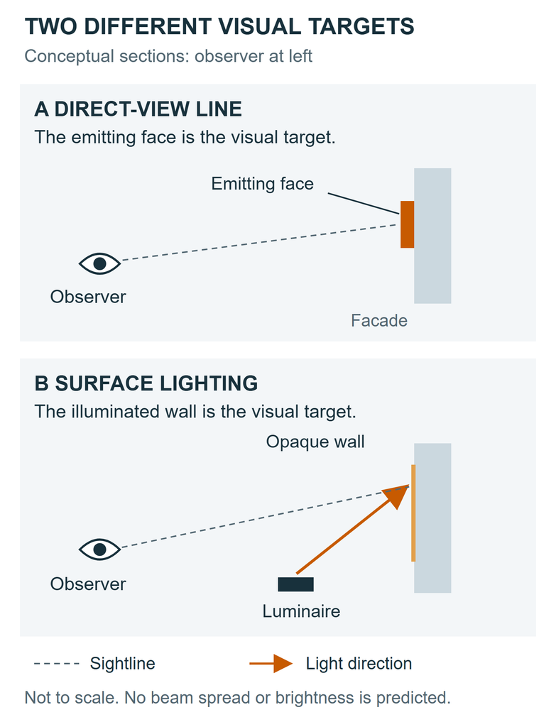
For glazed towers, identify the actual target: an opaque fin, a recessed detail or the emitting fixture itself. Do not assume that transparent glass will behave like an opaque wall. See the separate guide to glass curtain wall lighting for reflection and transmission considerations.
Establish a hierarchy from street level to the skyline
Choose which parts of the building deserve emphasis before repeating lights across every bay. Vertical lines can reinforce the tower’s proportions; horizontal bands can reveal setbacks or floor groupings. Neither arrangement needs to cover the entire elevation.
Evaluate three sets of views:
- Street and entrance views: check exposed sources, equipment visibility and the relationship with signs and shopfronts.
- Views from occupied floors and neighbouring buildings: check direct sightlines and reflected images of the lighting.
- Distant views: check whether the selected lines describe the building’s intended form, including corners and the crown.
A ground-level mock-up cannot fully represent a tower seen across a city. Use an elevation or three-dimensional study to assess the overall composition, then use physical samples to test local appearance. Renderings need suitable product and material inputs; they do not establish compliance or prove a continuous-looking line.
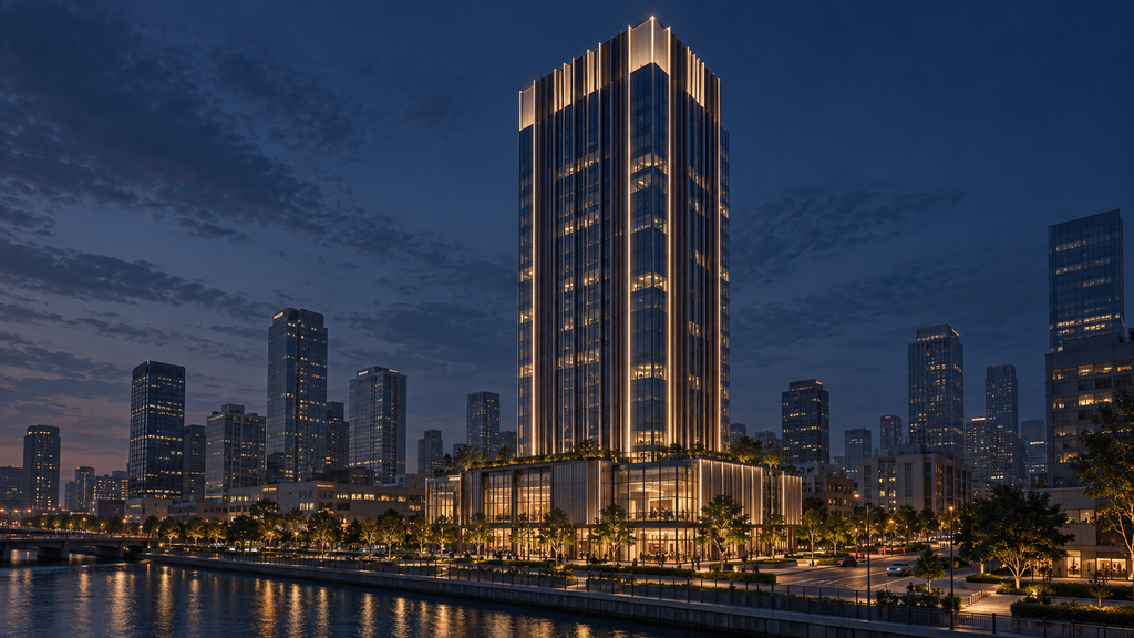
CRANE’s Lanzhou Centre project page describes separate lighting treatments for the tower crown and retail facade. It is a useful reference for distinguishing skyline and pedestrian scales, rather than a source of mounting dimensions or verified installations of the candidate products below.
Select positions using the complete facade section
Overlay lighting on the facade designer’s sections, not only the architectural elevation. Locate brackets, connector bodies, cable exits and equipment access before accepting a profile as suitable.
| Proposed location | Potential benefit | Condition that can invalidate it | Required check |
|---|---|---|---|
| Behind an opaque fin or reveal | Can conceal equipment from some directions | The feature blocks the intended light or leaves sources visible from other views | Test the actual section from both target and sensitive viewpoints |
| Along a horizontal ledge | Can establish a repeated band | Projection, drainage or maintenance operations conflict with the fixture | Coordinate the installed envelope, drainage paths and access equipment |
| At a curtain-wall mullion | Can align with the architectural grid | The visible cap is unsuitable for the proposed load or attachment | Obtain facade-system approval of the supporting and fixing arrangement |
| At the crown or a setback | Can create a distinct upper-level feature | Wind exposure, support capacity or replacement access is unresolved | Coordinate structural assessment, optical review and a maintenance method |
This is a location-screening method, not a fixing specification. Have the responsible engineer assess the load path from fixture and bracket into an approved support. A drawing of a clip does not demonstrate suitability for the building’s wind conditions.
Coordinate penetrations with the facade specialist so that lighting does not compromise drainage, weather seals or movement provisions. Confirm how a technician will remove a fixture and reach its connectors after the facade is complete, including clearance from facade-cleaning equipment.
Schedule modules around joints, ends and corners
Separate three dimensions: housing length, emitting length and installed length including connections and clearances. They are not interchangeable. A row of housings that fits a bay can still produce visible dark sections at its ends.
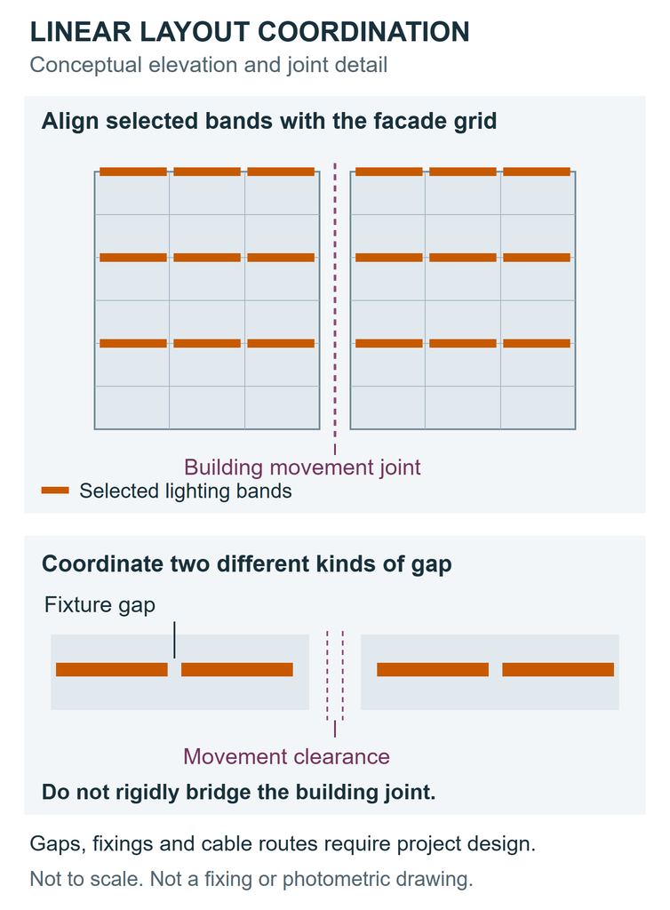
For each run, record the available architectural length, exact fixture quantities, approved gaps, end allowances and connection positions. If the arrangement does not fit, revise the module selection or the line termination. Do not remove required clearances simply to close a dimensional mismatch.
Distinguish ordinary gaps between fixtures from building movement joints. The first depend on the luminaire’s installation requirements; the second accommodate movement of the building or facade. Lighting supports must not unintentionally restrain that movement. Any crossing needs a coordinated detail, including the cable arrangement.
Figure 1. Coordinate lighting modules with the facade grid and movement joints. The example terminates fixtures on either side of the building joint. Conceptual illustration, not to scale; not a fixing detail or photometric result.
Do not apply one manufacturer’s thermal gap to a different fixture. Obtain the selected product’s instructions and the facade designer’s movement requirements separately.
At corners, review both elevations together. A detail acceptable from the front may expose an emitting end, create an apparent overlap or disappear from an oblique view. Include a corner and at least one module junction in the sample arrangement instead of testing only a single isolated fixture.
Separate visual runs from power and control runs
A visually continuous line does not have to be one electrical chain. Define the architectural effect first, then divide the installation into power and control runs using the selected system’s documented limits.
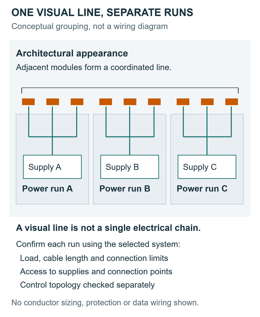
For a low-voltage system, confirm fixture demand, supply capacity, cable length and conductor size, voltage drop, connector ratings and the permitted number of connected fixtures. Check control topology and data limits separately. A controller’s addressing capacity does not establish how many fixtures a power circuit can supply.
Locate supplies and connection points where their environmental conditions and access requirements can be met. A shorter cable route is not useful if it leaves equipment inaccessible behind completed cladding. Record which physical fixtures belong to each supply and control group so a fault can be located without tracing the entire elevation.
Agree normal and late-night operating scenes around the intended use and surrounding properties. Check direct light and reflected light reaching sensitive views. More distant visibility alone is not a reason to increase output without reviewing the resulting glare and spill.
Compare CRANE profiles against the unresolved detail
The following groups are candidates for configuration review. Their catalogue names do not establish suitability for every high-rise facade, and their illustrative optical graphics are not measured lighting results.
XC Curtain Wall: compare the cable arrangements
XC Curtain Wall linear lights include CAL-XC24-I-M1-C1 and CAL-XC12-II-M1-C1. The page identifies an integrated cable channel in XC I, while XC II has a curved face without a cable channel.
This distinction matters where the facade provides limited space for a separate wiring route. Submit the actual section and compare the complete installed arrangement for each model. Request fixing and connection drawings, configuration-specific optical information and a sample for the intended viewing positions. An integrated channel does not by itself establish connector access, an acceptable movement detail or structural compatibility.
HL-XT KP Baffled: assess source visibility from a defined direction
HL-XT KP Baffled linear lights have aperture-style profiles with a raised side baffle. The page distinguishes these models from the standard versions and lists bracket-dependent installation heights.
Consider this construction when a particular viewing direction needs investigation. Confirm the complete model, baffle orientation, mounting envelope and emitting-face appearance with a sample. The page provides no quantified shielding performance, so the raised baffle should not be treated as proof of glare control or acceptable brightness from every direction.
Release the repeated layout only after representative checks
Before ordering the repeated runs, prepare a review package that connects the concept to an installation:
- An annotated elevation: identify fixture runs, module ends, corners, movement joints and areas intentionally left dark.
- Coordinated sections: show the selected profile, supporting construction, connectors, cable route and replacement access.
- A configuration schedule: identify the exact models, light-colour options, optics where applicable, supplies and control groups.
- A representative mock-up: review line appearance, junctions and source visibility at normal and reduced operating levels. Record viewing positions, background conditions and the tested settings.
- An acceptance record: distinguish accepted details from unresolved issues. Use photometric assessment for illuminated surfaces and appropriate visual or luminance assessment for direct-view elements; one check does not substitute for the other.
If a sample fails, identify the cause before increasing output. A dark junction may need a different module arrangement; an exposed source may need another position; a shadowed wall may need different optics. Repeating an unresolved detail multiplies the problem across the tower.
Frequently asked questions
Can rigid linear fixtures be cut on site to fit the last bay?
Only if the manufacturer expressly permits cutting for that exact product and provides a method for restoring the required construction and protection. Do not assume that a rigid luminaire behaves like cuttable LED tape. Where cutting is not permitted, review available lengths, a deliberate termination or a confirmed special configuration before procurement.
Will replacement fixtures match if their wattage and CCT are the same?
Not necessarily. Correlated colour temperature (CCT) and wattage do not fully define colour appearance or output. Existing units may also have aged differently. Record the original configuration and agreed colour-consistency requirements, then compare replacement samples at the intended operating settings before accepting a visually prominent substitution.
Does a DMX512 option mean that a linear light can display video?
No. A listed control protocol does not establish individually addressable segments, update performance or compatibility with a media-control system. Confirm the fixture’s channel map, controllable segment size and the complete control chain. A fixture controlled as one colour-changing unit cannot be assumed to provide independent pixels along its length.
How should a facade lighting scheme be handed over in phases?
Define which sections can operate independently and how incomplete connections will be protected. Give each commissioned section a documented fixture map, control configuration and operating scene. When later phases are added, review the combined appearance and settings; acceptance of one section does not establish acceptance of the complete elevation.
How should competing layouts be compared for energy use?
Compare equivalent visual objectives and operating schedules, not only watts per fixture. Include fixture quantities, power-supply losses and control equipment. Use documented consumption at the intended operating states or measurements where needed; a dimming command percentage is not necessarily the same percentage of input power. A lower-power proposal that requires more fixtures or longer operating hours may not use less energy overall.
Discuss a high-rise linear lighting layout
Contact CRANE about a proposed linear lighting configuration with facade elevations, mounting sections, required run lengths, viewing positions and power-access locations. Include movement-joint and maintenance constraints so the discussion can focus on candidate profiles and the evidence needed before specification.

Ethan Lee
Product Selection
Explore Lighting Products for Facade Projects
Compare product families by the lighting effect, mounting position and architectural detail you need to achieve.
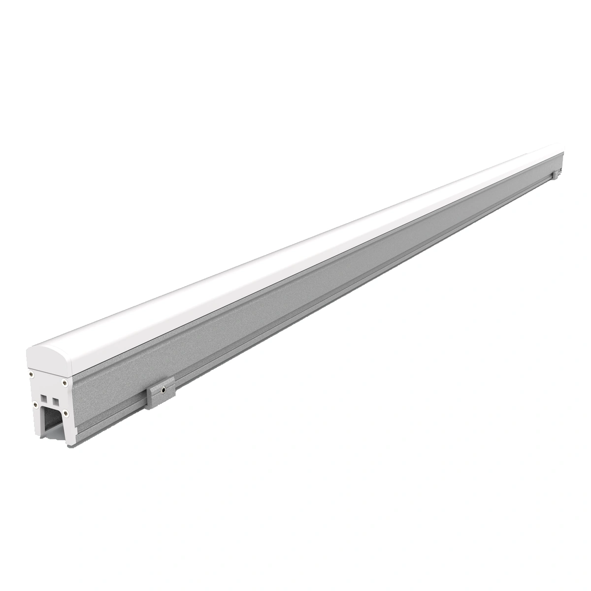
LED Linear Lights
Architectural LED linear lights with model-specific PC covers, glass faces or aluminium aperture-style profiles.
Browse Linear Lights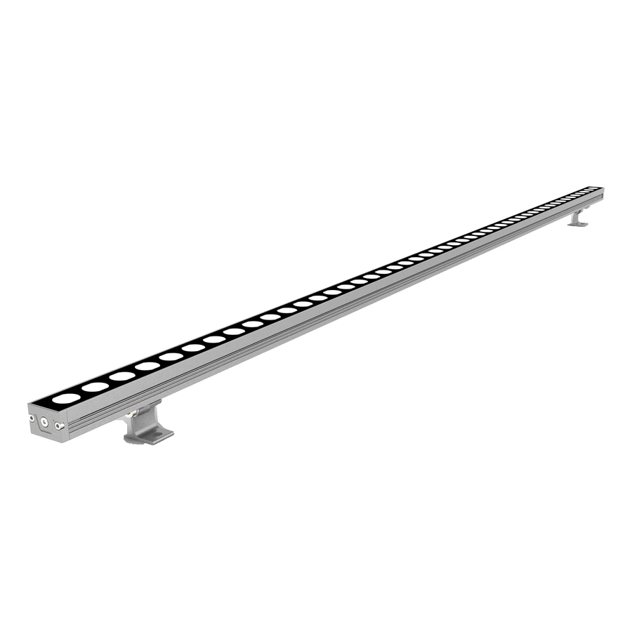
LED Wall Washer Lights
Architectural wall washer lighting for building facades, vertical surfaces and outdoor structures.
Browse Wall Washer Lights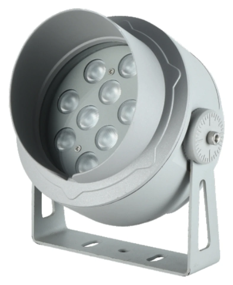
LED Flood Lights
Architectural LED flood lights for facades, landmarks, landscapes and outdoor lighting projects.
Browse Flood LightsExplore Facade Lighting Solutions
Related Project
See Facade Lighting in Practice
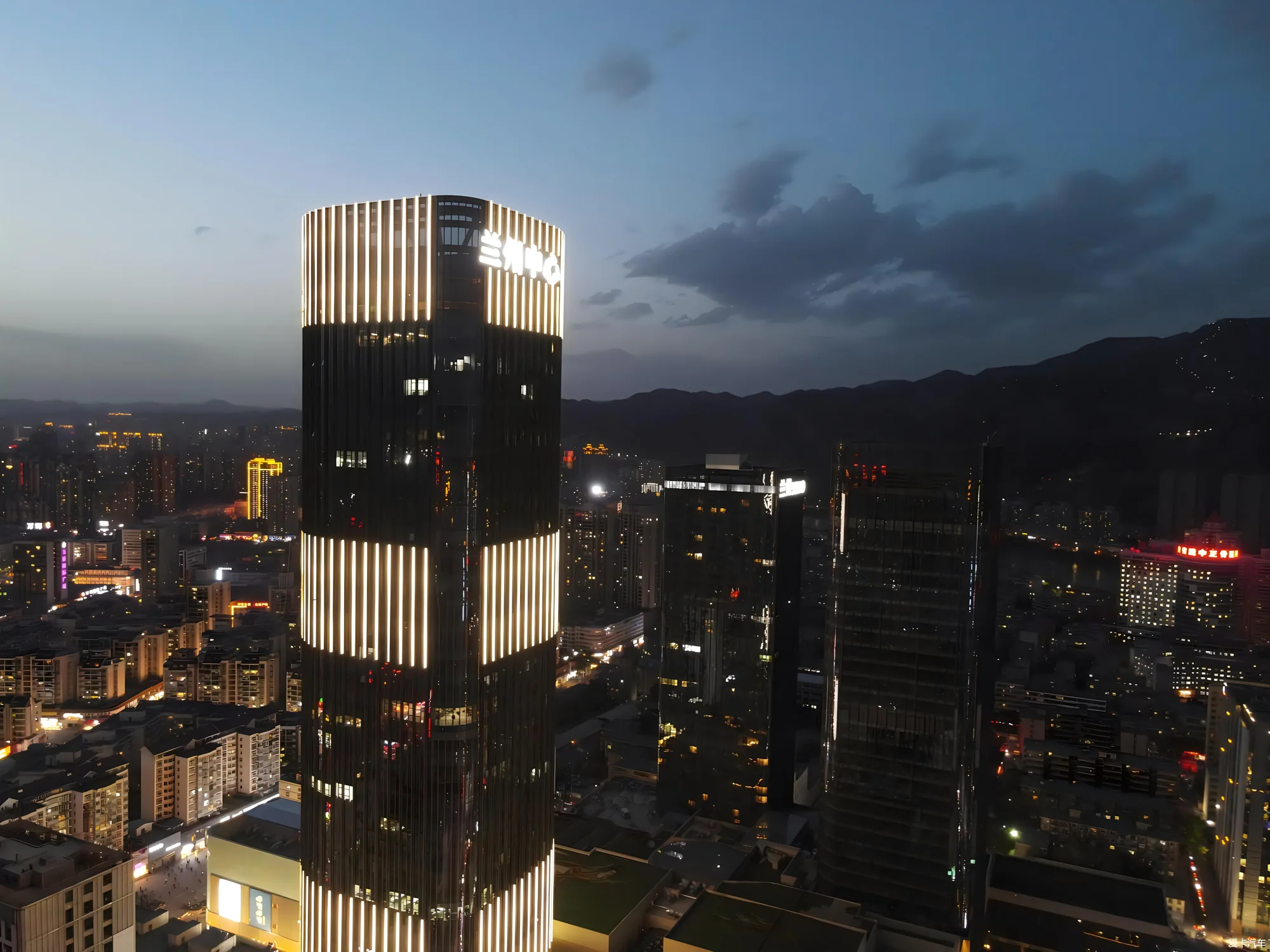
Lanzhou Centre
At Lanzhou Centre, illuminated vertical fins mark the tower crown and selected bands below, creating a clear silhouette above the commercial podium. Warm architectural lighting at street level gives the retail facade its own scale and identity.
View the Lighting ProjectProject Inquiry
Discuss Your Facade Lighting Project
Tell us about your facade, desired lighting effect and project requirements.