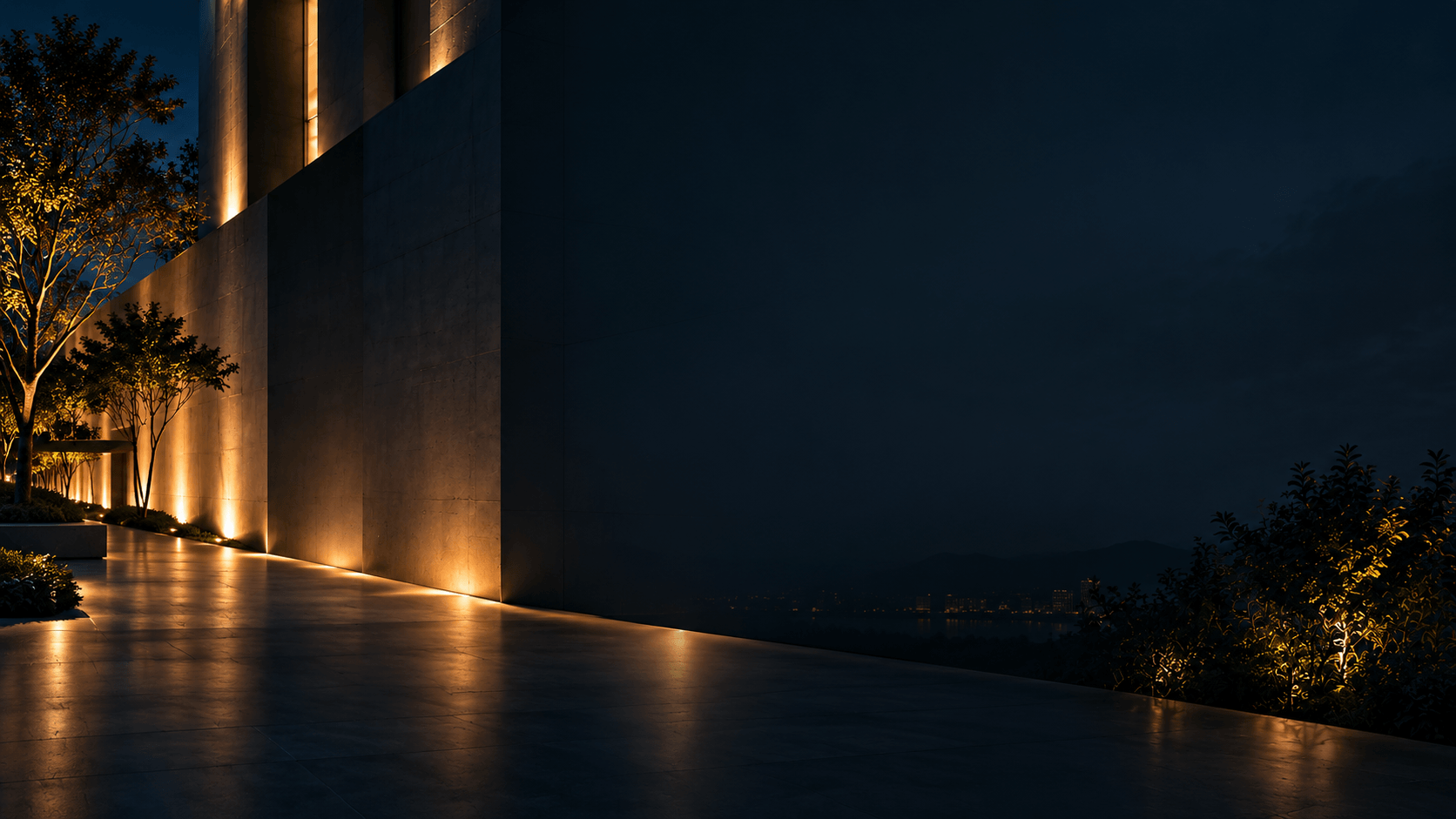
Effective glass curtain wall lighting starts with a defined target: opaque architectural elements, interior surfaces visible through the glazing, or luminous lines integrated into the facade. For transparent vision glass, broad external illumination is often a poor starting point because light can reflect toward observers or pass into occupied rooms without creating the intended surface appearance.
Choose the lighting approach around the actual glass assembly and mounting geometry. Then assess direct source visibility, reflected views and transmitted light separately, from both inside and outside the building. More output cannot compensate for an unsuitable light path.
Choose the target before the luminaire
Identify the intended appearance on the elevation and show how light reaches it in a section drawing.
| Intended appearance | Approach to investigate | Condition that can change the decision |
|---|---|---|
| Defined facade structure | Illuminate opaque fins, reveals or solid bands | The target may be too narrow to intercept the proposed distribution, or its finish may redirect light |
| Visible interior depth | Illuminate selected interior walls, ceilings or architectural volumes | Occupancy, blinds and interior lighting schedules change the exterior view |
| Luminous outlines or patterns | Integrate visible linear or point sources | Source brightness must be acceptable from nearby and oblique viewpoints |
| A glowing glazed surface | Develop lighting around suitable translucent or patterned glazing | The actual assembly must scatter light in a way that supports the intended effect |
Illuminating a mullion and creating a visible line of light are different tasks. The former depends on the light reaching and leaving a target; the latter depends on the appearance of the emitting surface itself.
Do not substitute clear vision glass for a translucent panel and assume the same lighting effect. Approve the glazing and lighting arrangement together.
Obtain data for the complete glazing assembly
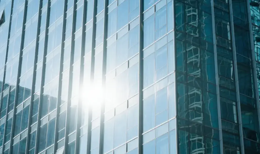
Glass reflects, transmits and absorbs incident light. Its response depends on substrates, coatings, interlayers and surface treatments. The relative lighting conditions on either side also affect what viewers notice: a reflective daytime facade may reveal illuminated rooms after dark, while interior reflections can interfere with views out.
Request visible light transmittance, exterior and interior visible reflectance, the glass build-up, coating positions and details of any tint or frit. Obtain relevant angular optical information where available.
Use data for the specified assembly rather than a single pane or a different coating configuration. A reflectance percentage is an input, not a glare verdict. Source luminance, apparent size, reflected position and background brightness still matter.
Trace the problem from the affected viewpoint
Start at the observer or receiving surface where the problem occurs. A complaint that the facade is too bright does not identify whether the cause is a direct view, a reflection or unwanted transmitted light.
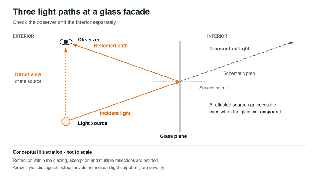
Direct, reflected and transmitted light paths require separate checks. Conceptual illustration — not to scale. Refraction within the glazing, absorption and multiple reflections are omitted.
| Observation | Mechanism to investigate | First diagnostic action | Evidence after adjustment |
|---|---|---|---|
| An exposed luminous line is uncomfortable | Direct source visibility | Inspect the source from the affected position | Repeat that view with the proposed shielding or output setting |
| A bright image appears in a pane | Reflection of a source or illuminated object | Identify the source and trace its reflected path | Check the original and adjacent viewpoints |
| Unwanted light reaches a room | Transmission through glazing | Switch candidate lighting zones off individually | Confirm the change at the affected interior location |
| Nearby windows receive unwanted light | Direct spill, reflected spill or both | Follow the complete route beyond the target | Reassess affected windows under the approved scene |
Locate potential reflected views
For a flat reflecting surface, incident and reflected angles are equal when measured from the surface normal. An initial check can connect the source, reflection point and observer in plan and section. Alternatively, mirror the source position across the glass plane and examine the observer’s sightline toward that virtual image.
This identifies a possible reflected view, not its severity. It does not fully represent multiple reflections within an insulating glass assembly. Curved and faceted glazing needs additional checks because the local surface orientation changes.
Isolate the contributing source
Record the observer’s position, viewing direction and operating scene. Switch candidate lighting zones off individually while keeping other conditions reasonably stable.
If the image remains, investigate interior lighting, signs or another exterior source. If it disappears, that identifies a contribution from the switched zone; it does not prove that other sources are irrelevant.
Retest any correction from the recorded position and nearby viewpoints. Moving the observer can make a reflection disappear without improving the installation.
Correct the light path before increasing output
If the intended surface is weakly illuminated, check whether it intercepts useful light. A narrow fin may receive only part of a beam while the remainder reaches glass or escapes beyond the facade.
A smaller nominal beam angle is not automatically a solution. Optical orientation, mounting position, aiming and the complete intensity distribution determine where the light goes.
Review these options in sequence:
- Reposition or re-aim the source, then check whether the problem transfers to another viewpoint.
- Review recessing or shielding against the relevant direct and reflected sightlines.
- Evaluate a distribution better matched to the target dimensions.
- Set the operating output and reassess the intended appearance and affected locations.
Dimming changes brightness but leaves the geometric path in place. Hiding a luminaire from a pedestrian’s direct view does not necessarily hide its reflection.
Review added accessories for compatibility, clearances, maintenance access and effects on luminaire operation. A field-made shield should not be assumed acceptable merely because it blocks one sightline.
Define the assessment locations and operating states
Mark intended targets and protected areas on the same drawing. Include occupied glazing, neighboring windows and relevant road-user viewpoints.
For each lighting zone, define the target, mounting arrangement, assessment locations, operating scenes and acceptance method. Agree who approves the result before procurement.
Distinguish illuminance, the light arriving at a surface, from luminance, the directional brightness of a surface or source. A receiving-plane illuminance result alone cannot characterize every reflected-glare concern.
Select outdoor-lighting criteria applicable to the project location and approval conditions. Do not transfer one limit or operating schedule from an unrelated project. Occupied and after-hours conditions should be assessed separately; tenant lighting and blinds should not be assumed to provide permanent screening.
Compare candidate products against the installation detail
The following CRANE families provide starting points for two distinct tasks. Neither establishes project suitability without a matching installation review.
XC Curtain Wall: integration and cable coordination
Consider XC Curtain Wall linear lights when the proposed effect uses a luminous line integrated into a facade detail.
The product page distinguishes XC I, with an integrated cable channel, from XC II, with a curved face and no cable channel. This affects the cable route and the section that must accommodate the fixture.
Provide the facade section and request the exact model drawing, fixing detail and applicable photometric data. The page’s optical illustrations do not establish model-specific intensity, uniformity or mounting distance. Do not treat either profile as a structural curtain-wall component or a confirmed fit for every system.
HL-XT KP Baffled: investigate directional shielding
Consider the HL-XT KP Baffled family where a raised side baffle may help screen an emitting surface from a defined direction.
The baffle is a verified construction feature. The available page does not establish a measured glare-reduction percentage or shielding result for the project.
Provide the critical sightlines and installation orientation. Request the exact drawing and assess a representative sample. A baffle that does not intersect the unwanted path cannot be assumed to address it.
If the task is to illuminate an opaque surface instead, review suitable optics separately rather than assuming that a visible-line product will provide the required surface illumination.
Use a mock-up as a decision test
A representative mock-up includes the specified glass, relevant framing, proposed luminaire and interior background. A generic clear pane cannot validate a different coated assembly.
| Test condition | Decision it supports |
|---|---|
| Interior lighting on, partially on and off | Whether the effect depends on occupied rooms |
| Blinds open and closed | Whether normal tenant behavior changes the result |
| Nearby, distant and oblique views | Whether the installation works beyond the presentation viewpoint |
| Interior views toward the glazing | Whether sources or reflections interfere with occupied space |
| Normal and reduced-output scenes | Whether realistic operation preserves the intended effect |
| Corners and changes in facade direction | Whether the repeated detail remains suitable at transitions |
In a hypothetical office project, exterior lines beside vision glass appear balanced while rooms are illuminated but become distracting after occupants leave. The next comparison should test revised shielding or an after-hours scene. Approval only under occupied conditions would leave the actual issue unresolved.
Record the accepted model, optic, mounting references, aiming, shielding and settings, together with viewing positions and interior conditions.
IES and LDT are photometric file formats used in lighting calculations. A matching file describes luminaire output, not the optical properties of the glazing. Confirm that any simulation represents the reflection and transmission behavior being assessed; an opaque diffuse-wall model cannot validate a transparent facade’s reflected appearance.
Photographs document the review, but exposure changes apparent brightness. Where numerical acceptance criteria apply, use appropriate measurements and record the method.
Frequently Asked Questions
Does low-E glass automatically reduce visible reflections?
No. Low-E means low emissivity and concerns thermal radiation performance. It does not establish a particular visible reflectance. Different low-E assemblies have different reflected and transmitted appearances. Obtain the visible optical properties of the specified assembly rather than using the low-E designation as a low-reflection guarantee.
Is a catalogue UGR value enough to approve exterior facade lighting?
No. Unified Glare Rating, or UGR, was developed for discomfort-glare assessment in interior lighting. Tabulated values depend on defined conditions. A catalogue value does not establish acceptable reflected glare from exterior glazing or compliance with outdoor obtrusive-light criteria. Use an assessment appropriate to the actual installation.
Can RGBW lighting behind glass reproduce a specified brand colour?
It may, but approve the colour through the actual glazing. RGBW refers to red, green, blue and white light channels; glass substrates and coatings can alter transmitted appearance. For a critical colour, test the complete combination and agree on a measurement method and tolerance. A controller setting alone is insufficient evidence.
Can window film correct an existing reflection problem?
Possibly, but film modifies the glazing system and is not a universal lighting remedy. Review reflection, transmission, absorption, compatibility and warranty implications. Changes in solar absorption can affect thermal stress, so obtain the glass fabricator’s and film supplier’s assessment before specifying a retrofit.
Can an indoor luminaire be installed behind the outer glass layer?
Only if it is suitable for the actual environment. A curtain-wall cavity is not necessarily a dry, temperature-controlled room. Confirm moisture exposure, temperature, ventilation, mounting arrangements and maintenance access with the manufacturer. Apparent shelter does not establish environmental suitability.
Will correcting nighttime lighting eliminate daytime solar glare?
No. Solar glare depends on the sun’s changing position, facade geometry and affected viewpoints. Changing a luminaire’s output or operating schedule does not change those solar reflection paths. A daytime concern requires a separate assessment covering the relevant locations, dates and times.
Discuss Your Glass Curtain Wall Lighting Requirements
Share your facade elevations and sections, glazing specification, proposed lighting positions and principal viewing locations with CRANE. Include the intended nighttime appearance, occupancy schedule and sensitive neighboring areas.

Ethan Lee
Product Selection
Explore Lighting Products for Facade Projects
Compare product families by the lighting effect, mounting position and architectural detail you need to achieve.
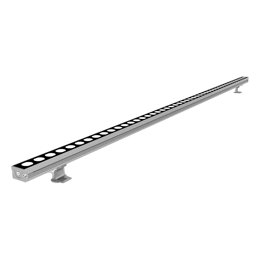
LED Wall Washer Lights
Architectural wall washer lighting for building facades, vertical surfaces and outdoor structures.
Browse Wall Washer Lights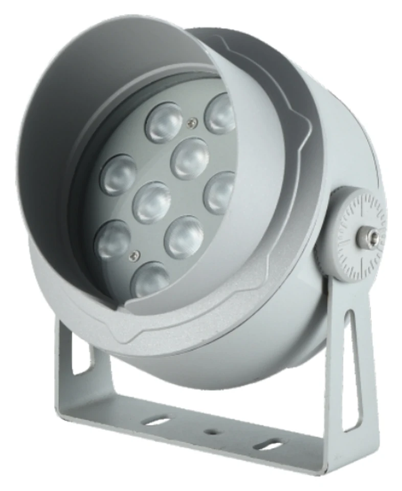
LED Flood Lights
Architectural LED flood lights for facades, landmarks, landscapes and outdoor lighting projects.
Browse Flood Lights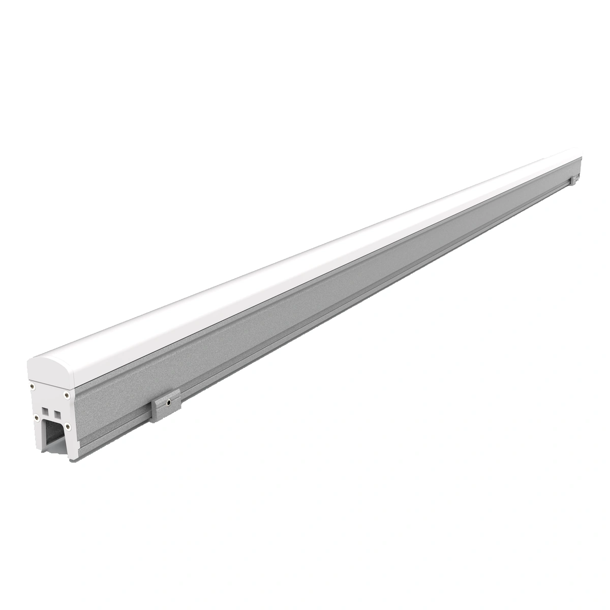
LED Linear Lights
Architectural LED linear lights with model-specific PC covers, glass faces or aluminium aperture-style profiles.
Browse Linear LightsExplore Facade Lighting Solutions
Related Project
See Facade Lighting in Practice
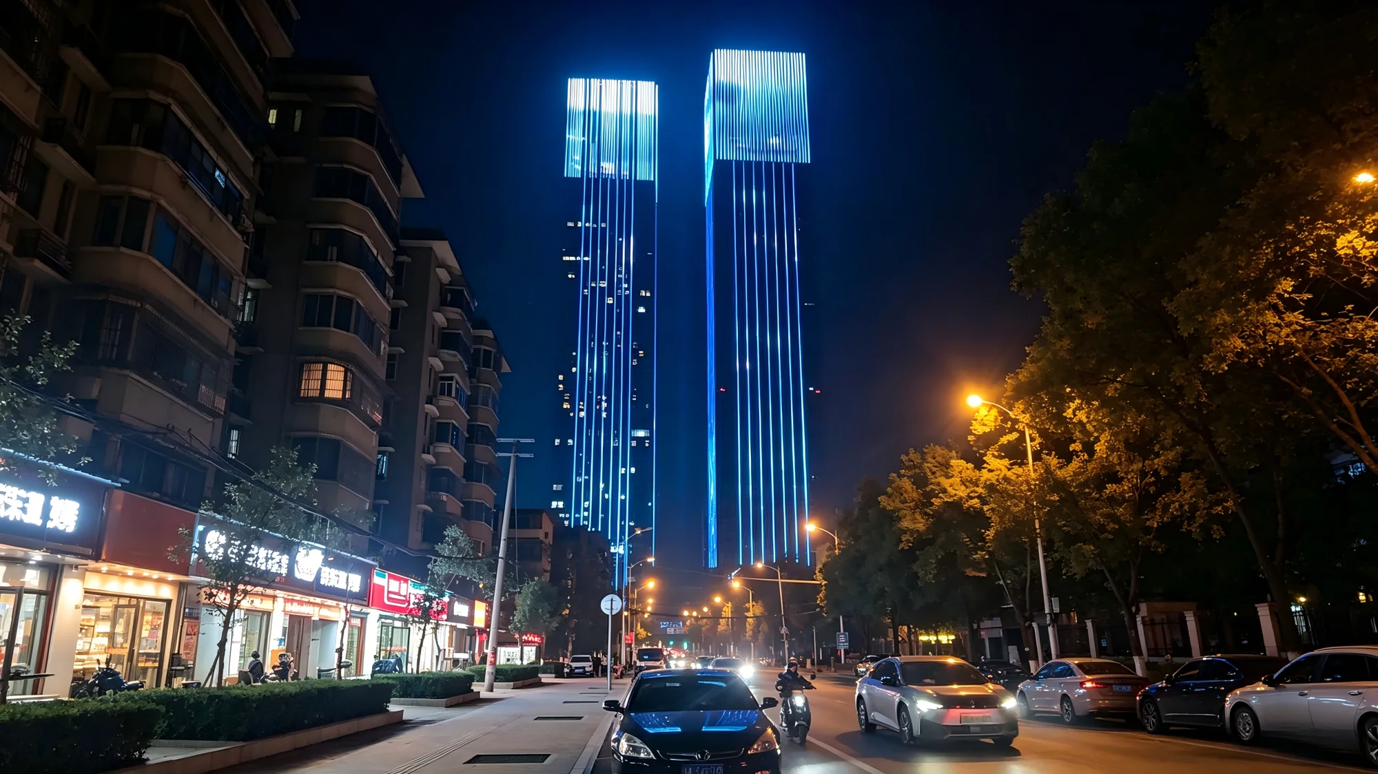
Changsha Jingtian Plaza
At Changsha Jingtian Plaza, vertical LED pixel lines follow the curtain-wall fins of two super high-rise towers. Graphics near the crowns and linear lighting along the podium give the development two distinct lighting scales, from the skyline to the street.
View the Lighting ProjectProject Inquiry
Discuss Your Facade Lighting Project
Tell us about your facade, desired lighting effect and project requirements.