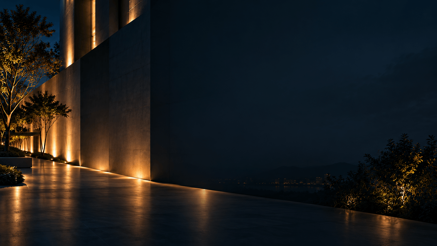
Reduce unwanted hot spots and light spill by checking where the luminaire is mounted, how it is aimed and how its complete light distribution meets the facade. Begin by identifying the exact problem area, then compare feasible changes to the optic, mounting position, aiming, spacing and compatible shielding. Verify the selected arrangement using the correct photometric data and, where practical, a night-time mock-up.
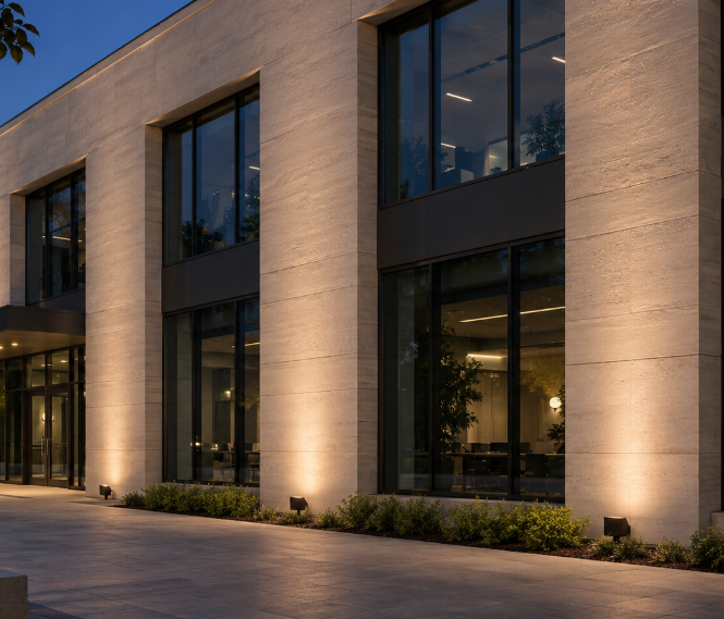
A bright patch near a luminaire and light reaching a window are different symptoms. A change that improves one can make the other worse, so assess the facade and its surroundings together rather than selecting a beam angle in isolation.
Identify the problem before changing the fixture
A hot spot is an unwanted area that appears noticeably brighter than its surroundings. It may be intentional accent lighting; it becomes a problem when it conflicts with the agreed visual effect or makes the facade appear uneven. A bright surface can reflect differently depending on its material and viewing angle, so appearance alone does not establish the cause.
Light spill is light falling outside the intended target. It can reach glazing, adjacent property, vegetation, roads or the sky. Glare concerns excessive brightness that affects a viewer’s comfort or vision. The visible source, its reflection and a bright patch on the wall require different checks, even when they occur together.
Record the symptom from agreed viewing positions, including nearby windows and public routes. Note the active scene, individual fixtures involved, mounting and aiming settings, ambient conditions and surface finish. Photographs taken with consistent camera settings help comparisons; they do not replace calibrated measurements when the project requires them.
Use the location of the bright patch to narrow down the cause
| Observed condition | Possible causes to investigate | First comparison |
|---|---|---|
| Bright band near the base or top of the wall | Close mounting, a concentrated distribution, aim or a recessed architectural detail | Compare the actual mounting section and aim with the selected optic’s data; trial a feasible change |
| Repeated bright and dark vertical bands | Fixture spacing, end gaps, individual optics or uneven aiming | Check fixture centres, orientation and the pattern from one fixture and adjacent fixtures |
| One unusually bright patch | A different setting, obstruction, reflective finish or installation variation | Compare that fixture and surface with adjacent positions before changing the whole row |
| Bright patch moves with the viewer | Reflection from glazing or a glossy surface may contribute | Inspect from several positions and review reflected source visibility |
| Upper wall is dark while the lower wall is bright | Distribution, throw, mounting position, aim or an obstruction | Compare vertical illuminance and wall coverage using the correct photometry |
These are diagnostic leads, not automatic diagnoses. For example, moving a fixture farther from a wall may change a near-base bright band, but the result depends on its optic and aiming. Confirm that the new location is physically available and does not increase spill or glare.
Trace spill beyond the intended target
Mark the illuminated architectural surface and the areas that should receive limited light. For upward-facing luminaires, inspect the roofline and the space above it; also check windows, property boundaries and nearby habitats where relevant. A distribution aimed near the top of a wall may still send light beyond the edge.
Identify which fixtures contribute to each unwanted area by testing them individually or in small groups when safe and practicable. A change to mounting position, tilt or distribution can redirect the pattern. A compatible shield, louvre or visor may also help control selected directions or direct views, but its effectiveness depends on the specific luminaire and orientation.
Shielding can alter output, distribution and thermal or maintenance conditions. Use accessories approved for the selected fixture and request photometric data for the assembled configuration when available. Do not assume a shield eliminates all spill or reflected light.
Choose a correction that fits both the wall and its surroundings
Position and aiming
Compare the installed position and aim with the approved drawings. Bracket projection, fixing tolerances and obstructions can change the illuminated pattern. Adjustments should remain within the manufacturer’s permitted range and the project’s physical constraints.
If the wall is too bright near the fixture and too dark farther away, changing the aim or setback may improve the balance. Check the whole wall and adjacent areas again: the revised aim may increase light above the roofline or toward glazing. If no feasible adjustment satisfies both conditions, consider a different optic or mounting arrangement.
Distribution and spacing
Review the complete distribution, not only a catalogue beam angle. Two products with similar nominal angles can differ in peak intensity, field light and side-to-side coverage. A dedicated wall-washing distribution or an elongated optic may be worth evaluating when it better fits the target and the available position.
For repeated bright and dark bands, test whether adjacent distributions overlap as intended. Verify spacing, fixture alignment, lengths and end gaps. Closer spacing can change overlap and increase combined illuminance, but it does not automatically fix a poor vertical distribution or an over-bright base.
Output and controls
Once the light reaches the correct surfaces, adjust output or scenes to meet the intended appearance. Reducing all fixtures equally can lower both a hot spot and the surrounding wall; it does not necessarily improve their relative contrast. Individually controlled zones may provide more flexibility, subject to the actual control system and fixture capabilities.
Compare options with a repeatable project check
The following workflow is useful for both a new project and a retrofit:
- Define the target. Mark the facade area, excluded glazing, roofline and key viewpoints. Record the intended visual effect and any project-specific limits.
- Document the baseline. Record fixture model, optic, position, setback, aim, spacing, accessories and control scene. Identify the unwanted bright area and where spill reaches.
- Verify product data. Obtain the IES or LDT file for the exact model, output, optic and accessory combination. Confirm the photometric orientation and any limitations of the file.
- Model feasible alternatives. Compare options on the same wall calculation area and grid. Examine vertical illuminance and areas outside the target; include relevant obstructions and other light where the model supports them.
- Check the trade-off. Record whether each option improves the wall, changes visibility of the source and moves light toward or away from sensitive areas. Do not accept a lower average as proof that a local hot spot has been resolved.
- Test and record. Where practical, trial a representative section after dark. Photograph and, if required, measure with a documented method. Record final positions, aim and control settings for the installation team.
Illustrative diagnosis
Imagine a row of uplights creates a bright lower band, while light from some fixtures reaches beyond the roofline. First confirm the installed tilt, position and scene. Then compare a feasible revised aim and a second optic using the same facade geometry and product-specific photometry. If the alternative reduces the lower contrast but increases spill above the roof, it does not resolve the complete problem.
Next assess whether an approved shield or a different mounting position can meet both objectives without hiding the desired upper wall. Validate the chosen combination on site. This is a hypothetical example, not a CRANE project or a measured result.
Review CRANE product candidates
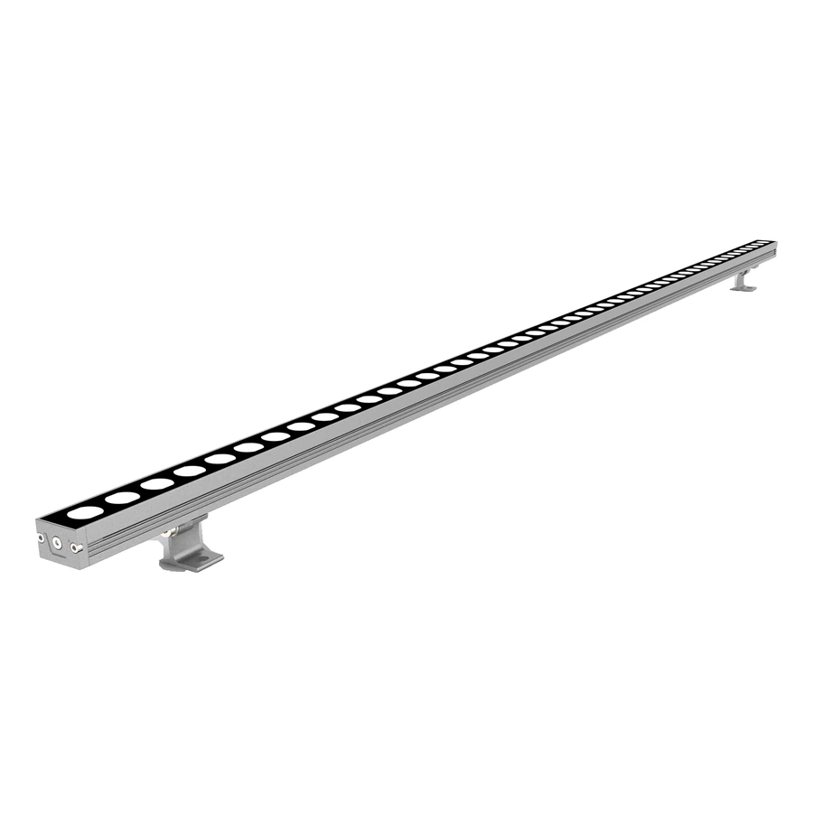
For a linear facade application, the CRANE LM 66 Multi-Row wall washer is a product candidate to review when its format and mounting conditions suit the wall. For an application where a floodlight position is available, compare the P Single-Module Architectural LED Floodlights with the project geometry.
For either candidate, confirm the specific model, optic, output, fixture location, aiming range and any compatible accessories. Request the corresponding photometric file and installation instructions. A product name or nominal beam angle alone does not establish that a particular hot spot or spill problem will be solved.
Frequently asked questions
Can cleaning a lens change an uneven facade pattern?
It can if dirt or an obstruction is affecting part of the output. Inspect and clean only as the manufacturer permits, then compare the result. Do not treat cleaning as a substitute for checking the optic and aiming.
Why can a facade look uneven even when measured illuminance is similar?
Surface colour, reflectance, texture and viewing direction can change the apparent brightness. Compare the readings with observations from representative positions and review the material, not just the calculation grid.
Can a shield fitted on site affect product compliance or the guarantee?
An unapproved modification can change the luminaire’s performance or interfere with its intended operation. Check the manufacturer’s instructions and project requirements before installation; ask about an approved accessory for the exact model.
What should be recorded before replacing only one fixture in a row?
Record its model, optic, output, colour configuration, accessory and aim. Confirm the replacement matches the approved configuration; a different distribution or output can create a visible discontinuity.
Does reducing light spill eliminate reflected light from the facade?
No. Controlling direct light beyond the target does not eliminate light reflected from the illuminated surface. Material, surface orientation and operating output all influence the reflected contribution.
How should a dynamic lighting scene be checked?
Review the representative scenes and operating levels that can actually be selected, including the brightest relevant state. A scene acceptable at one output or colour setting may need a separate check at another. Confirm the real control configuration before drawing conclusions.
Discuss your facade lighting conditions
Share the facade elevation, fixture locations, photographs of the affected areas, intended lighting effect and nearby sensitive viewpoints with CRANE. Include the proposed model and optic, or the details of the existing installation, so the appropriate product information can be reviewed.

Ethan Lee
Product Selection
Explore Lighting Products for Facade Projects
Compare product families by the lighting effect, mounting position and architectural detail you need to achieve.
LED Wall Washer Lights
Architectural wall washer lighting for building facades, vertical surfaces and outdoor structures.
Browse Wall Washer Lights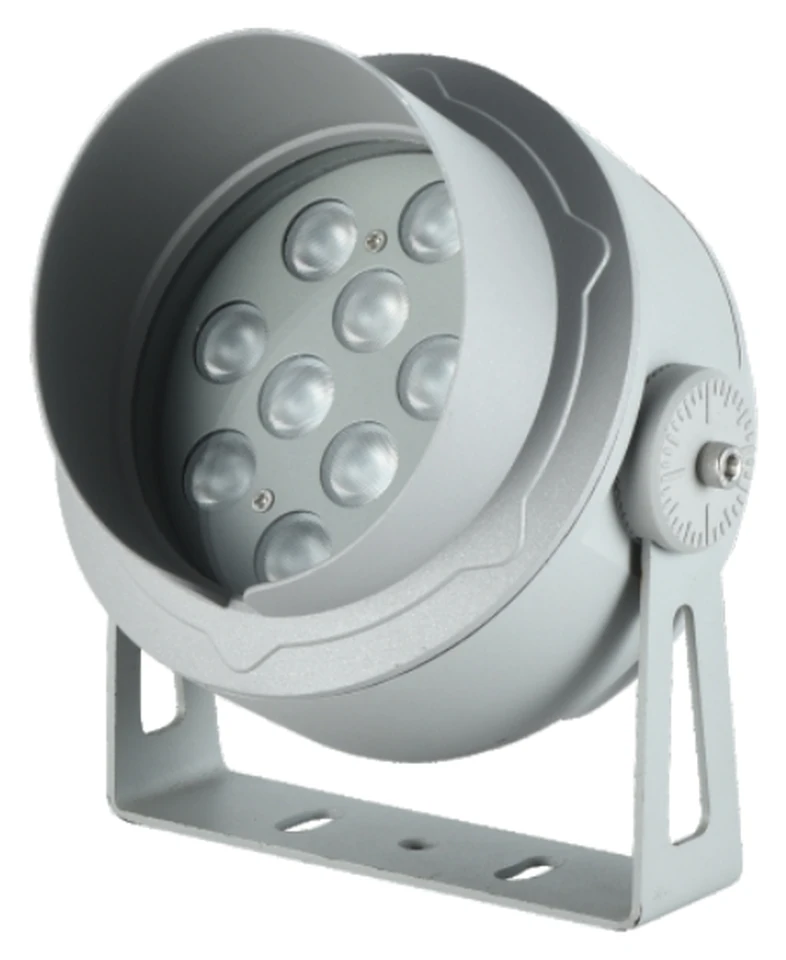
LED Flood Lights
Architectural LED flood lights for facades, landmarks, landscapes and outdoor lighting projects.
Browse Flood Lights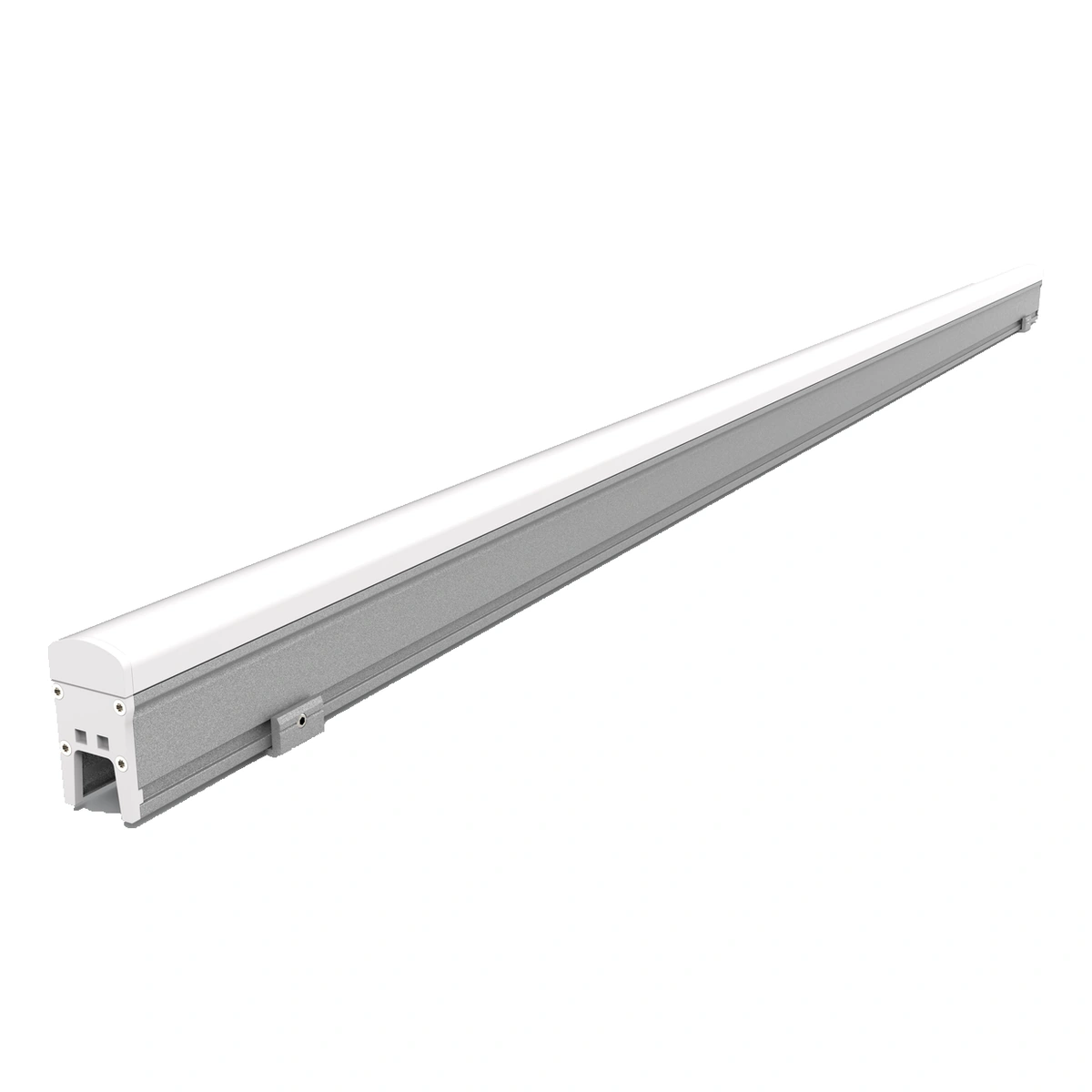
LED Linear Lights
Architectural LED linear lights with model-specific PC covers, glass faces or aluminium aperture-style profiles.
Browse Linear LightsExplore Facade Lighting Solutions
Related Project
See Facade Lighting in Practice
NOVATEK Commercial Complex
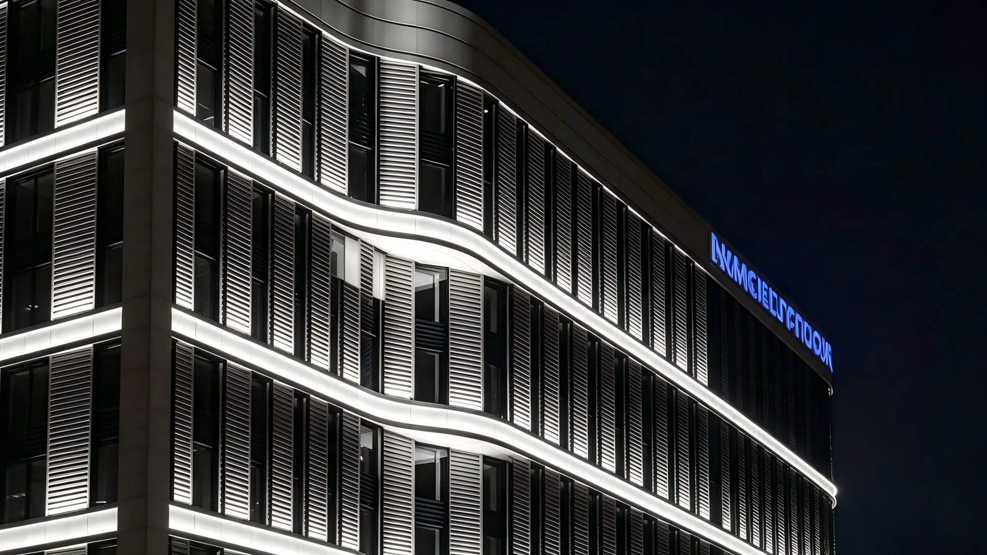
At NOVATEK Commercial Complex in Russia, continuous white lighting follows the building’s horizontal facade lines, turning smoothly around rounded corners. CRANE supplied LED wall washers and custom adjustable mounting brackets for the architectural lighting installation.
View the Lighting ProjectProject Inquiry
Discuss Your Facade Lighting Project
Tell us about your facade, desired lighting effect and project requirements.