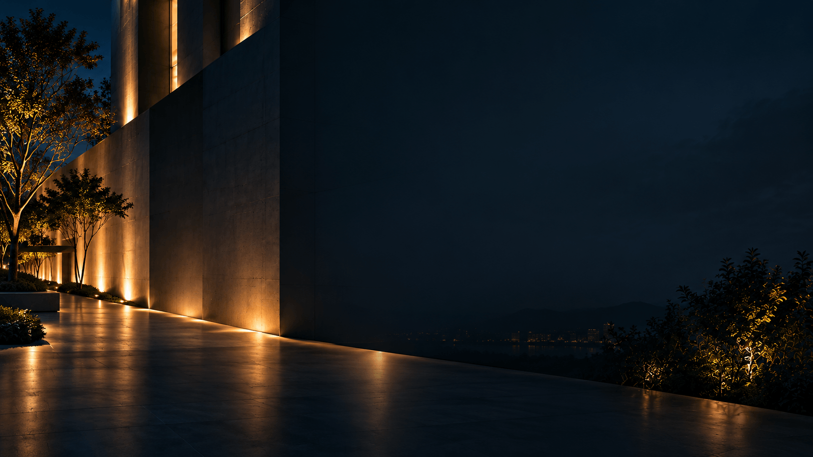
Calculate an initial LED wall washer layout from the wall dimensions, available mounting positions and the photometric distribution of the proposed fixture. Setback determines how far the fixture is from the wall; spacing determines how the fixtures are arranged along it. Adjust both together, then check the resulting illuminance and appearance with product-specific photometric data and, where practical, a night-time mock-up.
There is no single spacing or setback ratio that produces an even wash with every wall washer. The right arrangement depends on the optic, output, aiming, fixture length, surface and project acceptance criteria. A calculated fixture count is a starting layout, not proof of uniform illumination.
Define setback and spacing before calculating
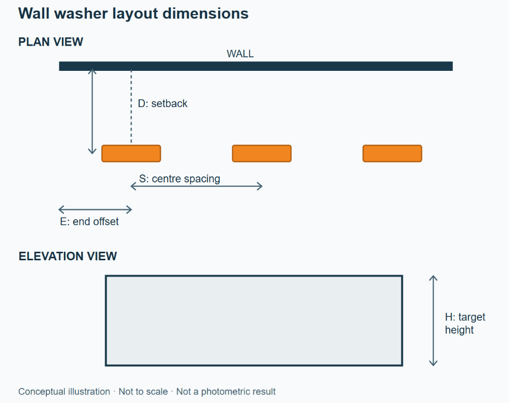
Setback (D) is the horizontal perpendicular distance from the selected fixture reference point to the wall plane. Record whether the drawing uses the optical centre, housing centre or mounting-hole position; these points can differ.
Spacing (S) is the centre-to-centre distance between adjacent fixtures along the wall. For linear luminaires, also record the fixture length and the physical end-to-end gap. These are different dimensions: for identical fixtures aligned end to end, centre spacing equals fixture length plus the clear gap.
End offset (E) is the distance from a wall end to the centre of the nearest fixture. Wall height is measured over the area to be illuminated, not automatically from the luminaire to the roofline.
Gather the inputs that control the result
| Input | What to record | Why it affects the layout |
|---|---|---|
| Target area | Wall width, height, corners, windows and excluded areas | Establishes the calculation surface and limits of the wash |
| Mounting | Available setback, mounting height, bracket and aiming range | Determines the actual source position and direction |
| Luminaire | Exact model, length, optic, output and photometric file | Defines the light distribution used in the calculation |
| Desired result | Target illuminance, uniformity, viewing positions and permitted spill | Provides criteria for comparing candidate layouts |
| Surface and surroundings | Finish, relief, obstructions and existing light | Influence appearance, shadows, reflections and visibility of spill |
The project team should agree on where uniformity is assessed. For example, excluding a narrow border changes the result; record any exclusions instead of comparing figures calculated over different areas. Surface illuminance alone does not determine apparent brightness, especially on glossy or strongly textured materials.
Establish a trial setback
Start with positions the building can physically accommodate, then review the manufacturer’s guidance for the exact optic. A close mounting position may emphasize texture and create a concentrated band near the fixture. Moving farther away can change coverage and reduce some near-field contrast, but can also introduce spill or require a different optic. The effect must be checked for the actual distribution and aim.
Manufacturer guidance is useful only within its stated context. For example, a recessed interior wall-washing system may have recommendations for a continuous line and a particular room height; those distances are not a design rule for outdoor linear uplights. If the available bracket cannot provide a proposed setback, do not assume the same calculation remains valid: compare another mounting arrangement or optic.
Calculate a first centre spacing and fixture count
For N identical, equally spaced discrete fixtures on a straight wall of width W, with equal end offsets E, their centres can be arranged using:
S = (W − 2E) / (N − 1), for N ≥ 2.
All dimensions must use the same unit. Conversely, if a trial maximum centre spacing Sₘₐₓ has been selected for evaluation, the initial count can be found using:
N = 1 + ceil[(W − 2E) / Sₘₐₓ].
Here ceil means round up to a whole number. This rearrangement gives a geometric arrangement only: Sₘₐₓ must come from an appropriate product-specific starting point or a trial to be tested. It is not a universal optical limit. Confirm that wall width exceeds twice the end offset and that the fixture bodies, brackets and required clearances fit.
Hypothetical worked example
Assume a straight wall is 12 m wide and the initial drawing places the outer fixture centres 0.6 m from each end. The team chooses 1.8 m as a trial maximum centre spacing for a hypothetical discrete fixture; this number is an assumption, not a recommendation or a CRANE product specification.
The distance between the first and last centres is 12 − 2 × 0.6 = 10.8 m. Dividing by 1.8 m gives six intervals, so the initial arrangement uses 7 fixtures. Its actual centre spacing is 10.8 ÷ 6 = 1.8 m.
Assume each fixture body is 1.0 m long and all are aligned. The estimated clear gap between adjacent bodies is 1.8 − 1.0 = 0.8 m. The outer body ends sit 0.1 m from the wall ends in this simplified arrangement. A negative gap or an end outside the available mounting area would require a different arrangement.
Now choose a trial setback that physically fits the bracket and site. The count calculation does not determine that distance or prove that seven fixtures illuminate the wall evenly. The hypothetical dimensions provide no lux values and are not a real project or a CRANE installation.
For a continuous linear run, start instead with the actual lengths and allowable joints. A row with minimal physical gaps can still show optical discontinuities due to end details or individual LED distributions; verify it using the product data and a sample.
Validate the trial with photometric calculations
Obtain an IES or LDT file that corresponds to the exact proposed model, optic, output and relevant accessories. Confirm whether the file’s luminaire orientation matches the way the fixture will be installed. An asymmetric optic can produce a misleading result if rotated or aimed incorrectly in the model.
Model the fixture positions and aims, wall plane, important obstructions and calculation area. Calculate vertical illuminance at a suitable grid of points and record the average, minimum and maximum over the agreed area. If the project uses minimum-to-average uniformity, calculate U₀ = Eₘᵢₙ / Eₐᵥg using the same grid and area for every option. The acceptable value must come from the project brief or applicable requirements; it is not established by this article.
Compare at least the proposed layout and a feasible alternative when a requirement is not met. For example, reduce the centre spacing and recalculate; if the upper wall remains too dark, consider whether mounting, aim, optic or output must change. Adding fixtures along the wall may address horizontal variation while leaving the vertical distribution unresolved.
Check the wall ends, corners, windows and observer positions separately. Averages can conceal a local bright patch or excessive light on glazing. Direct-light-only calculation tools have limits: surrounding surfaces, reflected light and other sources may require a fuller model. Use the same assumptions when comparing options, then check the sensitivity to realistic mounting tolerances.
Check the installation with a representative sample
Where the appearance matters, trial the chosen configuration on a representative section after dark. Include adjacent fixtures and their intended end-to-end arrangement so overlap can be observed. Mark the real setback, fixture centres and aiming settings; check from the agreed pedestrian, traffic and occupied-building viewpoints.
Compare the installation with the approved model and, if project acceptance includes measurement, use a suitable calibrated meter and a documented grid and procedure. Surface finish, ambient light and construction tolerances can alter the visible result. Record any adjustment and update the layout before the full installation.
Review CRANE wall washer candidates
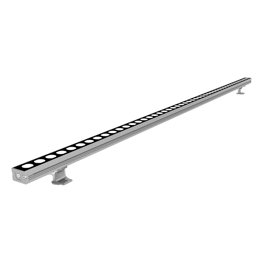
The CRANE LED wall washer lights category provides a starting point for identifying facade lighting products. The LM 66 Multi-Row product page presents a multi-row wall washer as a candidate for comparison where its format and mounting arrangement suit the facade.
Before using any LM 66 configuration in a layout, confirm the selected model, actual fixture length, optic, output, bracket geometry and aim. Obtain and verify the corresponding photometric file and mounting instructions. The existence of a product page or file link does not establish a specific setback, spacing or expected uniformity for your wall.
Frequently asked questions
What if fixtures cannot be placed equally because of columns or windows?
Model the actual positions and obstructions instead of forcing the equal-spacing equation. Assess the interrupted areas and adjacent surfaces individually; a different optic, mounting location or local treatment may be needed.
Should fixture spacing be measured from the housings or the light sources?
State the reference explicitly. Centre-to-centre spacing is useful for arranging identical fixtures, while housing end-to-end clearance is needed for installation. Where the optical centre differs from the housing centre, use the manufacturer’s geometry in the photometric model.
Can dimming fix uneven wall illumination?
Dimming a group of luminaires together changes output but does not necessarily correct the relative distribution across the wall. Individually controlled luminaires may help in some layouts, but optical mismatch, mounting and aiming should be addressed in the calculation first.
How should wall corners be handled?
Treat each wall plane and the corner region as part of the design. Check whether light from both runs overlaps at the junction, whether fixtures can physically fit, and whether the corner becomes brighter or darker than adjacent areas.
Can an IES file be scaled to represent a different fixture length?
Do not assume so. The relationship depends on the actual product construction and photometric data. Request a file for the selected length and configuration, or obtain a documented modelling method from the manufacturer.
What should be checked after a bracket or optic substitution?
Update the model to reflect the new optical centre, setback, aiming adjustment and photometric distribution. Also check physical mounting and clearance. A substitute with similar dimensions or wattage may not produce the same result.
Discuss a wall-washing layout with CRANE
Share the wall elevation, target area, proposed mounting section, available setback, desired effect and any restrictions on spill or glare. Identify the candidate model and optic so the appropriate configuration and photometric information can be reviewed for the layout.

Ethan Lee
Product Selection
Explore Related Lighting Products
Compare product families by the lighting effect, mounting position and architectural detail you need to achieve.
Project Inquiry
Discuss Your Facade Lighting Project
Tell us about your facade, desired lighting effect and project requirements.