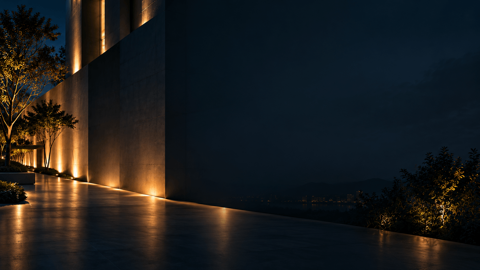
Install an outdoor LED wall washer from an approved layout that coordinates the exact luminaire and optic with the facade, mounting structure, power supply and control system. Confirm the wall offset, fixture spacing, aiming range, cable route and environmental exposure before fixing the first run. A representative mock-up and night-time review can reveal problems that a drawing alone cannot resolve.
A qualified electrical professional should install and commission the system in accordance with the product instructions and applicable local requirements. Isolate and verify the absence of power before electrical work. The steps below form a planning and inspection framework; the selected product’s instructions govern its connections and mounting details.
Establish the installation geometry
Start with the intended illuminated area and the positions where fittings can actually be mounted. Record facade height and length, surface changes, mounting elevation, available wall offset, obstructions, access and principal viewing positions. Compare these with the selected optic’s photometric data and the installation drawings.
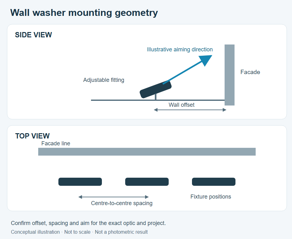
Wall offset is the horizontal distance from the fitting’s reference position to the facade. Spacing describes the distance between adjacent fittings, measured from a consistent reference point. Aim describes the installed orientation of the luminaire. Agree the reference points on the project drawing because brackets, housings and optics do not necessarily share the same centreline.
Do not transfer an offset or spacing ratio from another product without checking its optic and test basis. The same mounting line can produce different coverage when the optic, wall height or aiming changes. For a continuous wash, check the full height and the overlap between neighbouring fittings. On textured surfaces, close mounting may emphasise shadows rather than create a smooth appearance.
Use a short trial run to resolve the layout
Before repeating fixings across a facade, select a representative section that includes a joint between fittings and any relevant texture, recess or obstruction. Install a sample using the proposed mounting arrangement and temporary supply only under the project team’s approved electrical procedure. Observe it after dark from the intended viewing positions.
| Observation | Check first | Possible next action | Verify |
|---|---|---|---|
| Bright band near the fitting and weak coverage higher up | Mounting offset, actual aim and optic identification | Adjust the approved mounting position or compare another optic. | Inspect the full target height and adjacent fitting overlap. |
| Repeated bright or dark vertical bands | Fixture spacing, alignment and obstruction by brackets or facade details | Recheck centre-to-centre positions and the mounting line. | View the trial section from the principal approaches. |
| Distracting texture or shadows | Surface finish, wall offset and light direction | Compare a revised position or distribution against the intended appearance. | Inspect the actual material and an oblique viewpoint. |
| Light reaches windows or neighbouring areas | Aim, shielding, glazing and observer positions | Review aiming or a manufacturer-approved accessory. | Check the affected viewpoints and spill area at night. |
These are diagnostic starting points, not proof of a single cause. If an adjustment cannot be made within the approved bracket range, fixing constraints or project criteria, revise the layout or product selection. Record the accepted fitting, mounting references, aim and photographs before completing the run.
Fix and aim the fittings
Confirm that the substrate and fixing method can support the installed assembly and expected site loads. Coordinate anchors, corrosion exposure, waterproofing interfaces and penetrations with the responsible project disciplines. Check the mounting surface for straightness and allow access to bracket fasteners, cable connections and future replacements.
Set out the line using the approved reference points and identify deviations before drilling. Fit the manufacturer’s intended bracket and hardware for the selected configuration. Where a fitting is adjustable, set its orientation using the product’s adjustment method, then secure it as instructed. Do not use a torque value or permitted aiming range taken from another luminaire.
For limited installation space, CRANE HL Slim-Width is a candidate to review. Its product page identifies two models and shows that mounting options and installed height differ. Compare the actual model, bracket clearance and cable route with the available section. Request the current installation instructions, dimension drawing and photometric file for the exact configuration before approving its position. The LED wall washer range can be used to compare other product families when the required space or lighting effect differs.
Plan power, control and outdoor connections
Identify the luminaire’s actual electrical input and its required driver or power supply from the nameplate and documents. Some systems use a remote driver or controller, while others accept a different supply arrangement. Do not infer the connection from the fixture’s appearance or wire colours alone. Use the exact wiring diagram, connector pinout and compatible equipment specified for the configuration.
Prepare a circuit and control schedule showing the source, protective devices, driver locations, fixture quantities and cable routes. Have the electrical designer check loading, conductor sizing, voltage drop and protective arrangements against the equipment instructions and local rules. Confirm separately whether power and control circuits may share a route, and follow the control manufacturer’s requirements for topology, addressing and termination. There is no universal number of fittings per run.
Assess the environmental exposure of the luminaire, glands, cables, connectors, junction boxes and any remote driver enclosure at their own installed locations. Use compatible components and the specified sealing method. Orient entries and route cables as instructed, including a drip loop where appropriate and permitted. Keep connections accessible and away from locations likely to retain water. Cap unused connectors with the specified parts. An IP marking on the luminaire does not automatically extend to a separately assembled connection.
Inspect, commission and hand over
Before energizing, the responsible installer should inspect fixings, mounting orientation, cable protection, connector engagement, sealing, circuit identification and access. Carry out the electrical checks required by the design, equipment instructions and local rules using suitable instruments and procedures. Resolve faults before energizing.
After electrical checks, test each circuit and control function. Compare the installed aim and spacing with the approved sample. At night, review the complete facade and transitions between fittings from the agreed viewpoints; record unwanted spill, visible gaps, reflections and control or colour inconsistencies. Adjust only within the approved mechanical and electrical limits, then secure the setting.
Hand over the final drawings, exact product and accessory references, circuit and control schedule, approved aiming record, relevant test results, maintenance instructions and unresolved items. Document replacement and cleaning requirements so that the approved appearance can be restored after service.
Frequently asked questions
Can I install wall washers before the facade finish is complete?
Coordinate with the project team first. An unfinished surface can change the final wall offset, anchor detail and appearance. Protect any installed equipment during construction and confirm the final setting after the finish is complete.
Can the same brackets be used for every wall washer in a range?
Not necessarily. Check the exact model’s mounting drawing, approved bracket, installed envelope and compatible fixings. A shared product-family name does not establish interchangeable hardware.
Can I connect all fittings to one driver?
Only if the selected system permits that arrangement. Check the driver output, compatible fixture configuration, total load, cable voltage drop and manufacturer limits. The electrical designer should approve the circuit.
What if there is no room for the specified wall offset?
Measure the actual clearance and compare alternative mounting positions or optics with the lighting designer and supplier. Verify any revised arrangement with the appropriate photometry and, where warranted, a representative mock-up.
Can a damaged outdoor connector be repaired with tape?
Follow the manufacturer’s repair or replacement instructions. The completed connection must be suitable for its exposure and compatible with the supplied cable and connector system; tape alone should not be assumed to restore the tested assembly.
Why does the wall look different from the lighting rendering?
Check that the model used the correct photometry, mounting positions, surface assumptions and aiming. Compare those inputs with the installation and actual material. A rendering is a prediction based on its inputs, so resolve discrepancies with site observations and the design team.
Discuss your installation
Contact CRANE with the facade elevation and section, selected or proposed luminaire, available mounting space, desired effect, supply and control requirements, and cable route. Ask for the matching installation details and photometric documentation for the configuration under review.

Ethan Lee
Product Selection
Explore Lighting Products for Facade Projects
Compare product families by the lighting effect, mounting position and architectural detail you need to achieve.
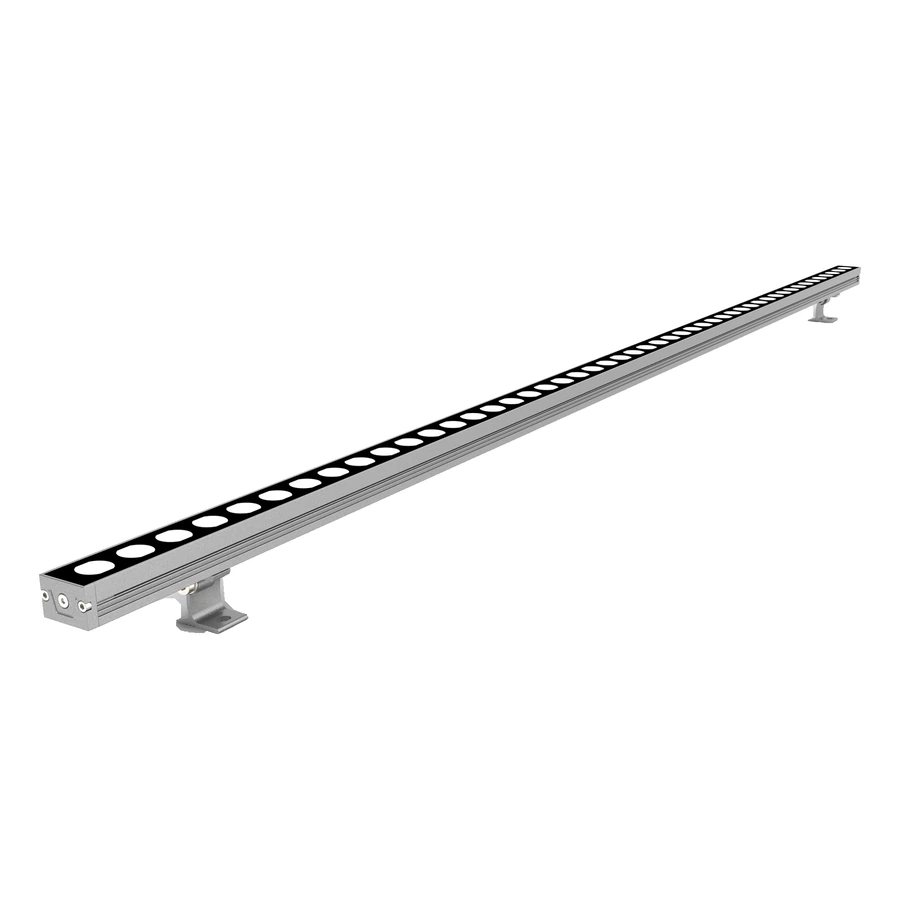
LED Wall Washer Lights
Architectural wall washer lighting for building facades, vertical surfaces and outdoor structures.
Browse Wall Washer Lights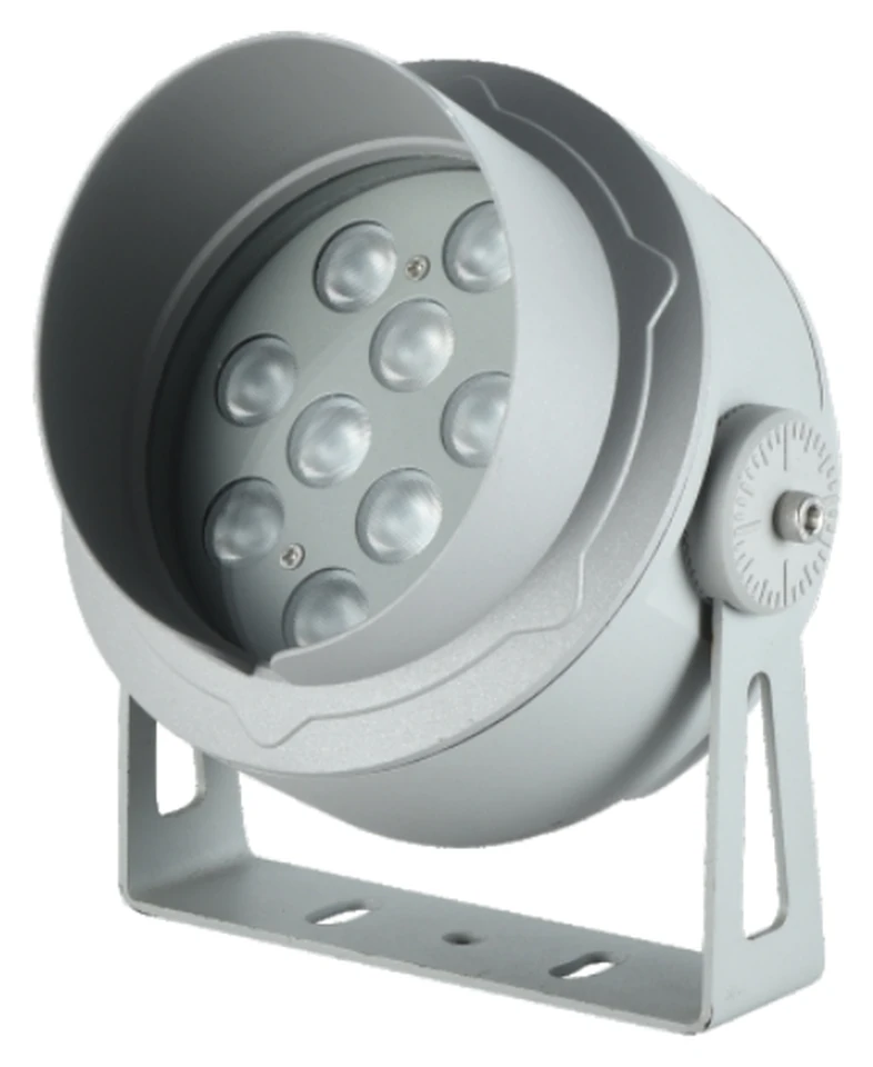
LED Flood Lights
Architectural LED flood lights for facades, landmarks, landscapes and outdoor lighting projects.
Browse Flood Lights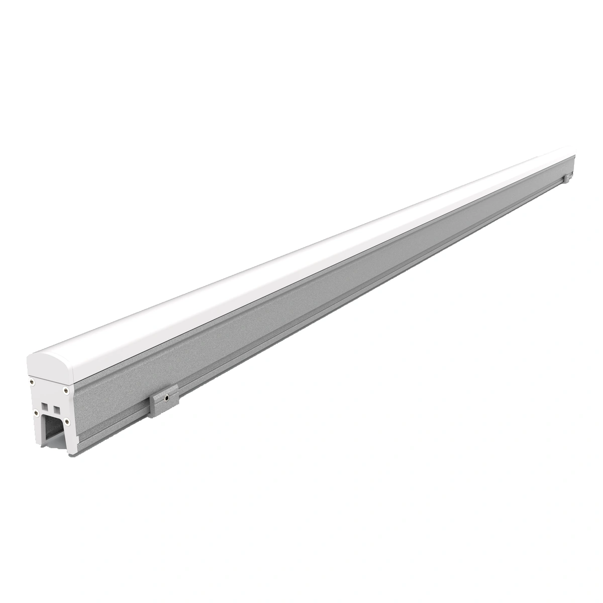
LED Linear Lights
Architectural LED linear lights with model-specific PC covers, glass faces or aluminium aperture-style profiles.
Browse Linear LightsExplore Facade Lighting Solutions
Related Project
See Facade Lighting in Practice

NOVATEK Commercial Complex
At NOVATEK Commercial Complex in Russia, continuous white lighting follows the building’s horizontal facade lines, turning smoothly around rounded corners. CRANE supplied LED wall washers and custom adjustable mounting brackets for the architectural lighting installation.
View the Lighting ProjectProject Inquiry
Discuss Your Facade Lighting Project
Tell us about your facade, desired lighting effect and project requirements.