DMX512 is a digital control protocol that sends instructions from a controller to compatible lighting equipment. In an architectural project, it can be used to change parameters such as intensity and colour when the selected luminaires or their drivers support those functions. The controller, signal distribution, fixture addressing, power supplies and control scenes must be planned as one system.
DMX512 carries control data, not the power needed to operate a luminaire. It also does not by itself provide scheduling, a user interface or proof that different products will interpret every channel in the same way. Those capabilities depend on the equipment and configuration chosen for the project.
How a DMX512 system controls architectural lighting
A controller sends a repeating stream of control values over a DMX data link. A compatible receiver—inside a luminaire or in a separate decoder or driver—reads the slots assigned to its starting address. Its channel mode determines what those values mean.
For example, a controller can send values used by compatible fixtures to create a static white scene or a colour-changing facade. The scene is created and played by the control system; DMX512 is the communication method used to deliver its values to the receivers.
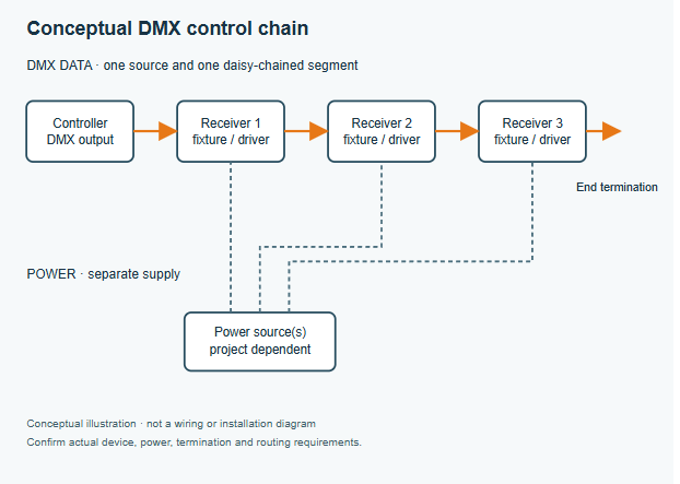
The diagram below shows one conceptual arrangement. Actual equipment may integrate several functions into one enclosure, and the power architecture depends on the selected products.
| System element | What to verify |
|---|---|
| Controller or gateway | Number of DMX outputs, scene playback, scheduling and interfaces required by the project |
| DMX distribution | Data topology, compatible cable, splitter locations, termination and receiver limits |
| Luminaire or decoder | DMX mode, channel map, addressing method, signal-loss behaviour and compatibility |
| Power system | Input voltage, driver or power-supply arrangement, load and protection requirements |
| Commissioning | Address schedule, scene settings, test procedure and handover records |
Understand channels, addresses and universes
A DMX512 universe carries up to 512 data slots, often called channels. Each conventional 8-bit slot carries a value from 0 to 255. A fixture may use one or more consecutive slots depending on its selected mode. The starting address identifies the first slot it reads.
A single luminaire can consume more than four channels. Some modes add overall intensity, effects, additional colour emitters or finer control. The manufacturer’s channel chart—not the label “RGBW” alone—establishes the actual footprint and channel order.
Multiple compatible receivers can intentionally share the same address range and respond together. That saves address space but removes independent control for those receivers in that mode. If independent control is required, assign distinct, non-overlapping ranges within the universe.
An illustrative capacity check
Assume a hypothetical facade uses 30 independently controlled fixtures, each confirmed to use a four-channel mode with no additional channels. The total is 30 × 4 = 120 channels. If allocated consecutively from address 1, their ranges run from 1–4 through 117–120. These are assumed devices, not CRANE product settings.
The remaining universe capacity is 512 − 120 = 392 slots before any other allocations or reserved capacity. This is a channel budget, not permission to put all 30 receivers on any physical cable run. Receiver electrical loading, cable type and length, splitters, power and manufacturer instructions are separate design checks.
If the same fixtures are instead configured in a documented eight-channel mode, they need 240 slots. If a required range would extend past slot 512, revise the allocation or use an additional universe with the appropriate controller output or gateway; do not assume a fixture can span universes.
Plan signal routing separately from power
A typical DMX data segment follows a daisy chain: source to receiver, then onward to the next receiver. Where the project needs branches, use a suitable active splitter or distribution device rather than an improvised passive Y connection. A splitter can distribute a universe to several physical branches; this does not automatically create additional independent channel capacity.
Terminate the end of each applicable data segment as required by the devices and system design. A common implementation uses a 120 Ω termination across the data pair at the last receiver; some equipment provides termination internally. Confirm the exact terminal positions, polarity, common conductor and termination method in the relevant manuals.
Select cable and connectors suitable for the installation and supported by the equipment. An RJ45 connector does not make a DMX signal Ethernet; pin assignments and the signal protocol must match at both ends. The permitted cable length and receiver loading depend on the hardware and topology, so use the manufacturer’s documented limits and the project design rather than a generic distance guarantee.
Power distribution is designed independently: check the supply, driver ratings, electrical protection, outdoor connection details and local requirements with a qualified installer. The data chain in the illustration is not a power wiring diagram.
Decide whether DMX fits the project’s control needs
DMX is useful where a project needs coordinated intensity or colour changes across compatible fixtures. It can support static scenes as well as changing effects, provided the chosen controller and fixtures offer the necessary functions.
Before selecting it, define how the building will operate after handover. Is a simple scheduled scene sufficient, or must an operator change scenes from a building-management interface? Who can edit the program, and what should happen after power or signal loss? Those answers determine the required controller, gateway, interfaces and documented fallback behaviour—not just the fixture protocol.
Standard DMX512 is normally a one-way control stream. Do not assume it reports fixture status. Remote Device Management (RDM) is a separate, related protocol; its availability requires compatible devices and supporting infrastructure throughout the relevant path. Confirm actual support instead of assuming every DMX fixture or splitter provides it.
Check compatibility before procurement
Build a schedule that ties each lighting zone to a specific luminaire and mode. Include the quantity, independent control groups, starting addresses, channel footprint, controller port or universe, driver, supply and cable route. Request the manufacturer’s channel chart and installation instructions for the exact configuration.
For mixed equipment, verify connector pinout, data polarity, dimming and colour-channel behaviour, and the intended response to loss of signal. Two products labelled DMX512 may use different channel maps or control modes. If they share an address, confirm that each interprets that range as intended.
Test one representative combination of controller, distribution device and luminaire before committing to a large installation. Record the selected mode and firmware where relevant. The goal is to find integration issues before the fixtures become difficult to access.
Review a CRANE product candidate
For a facade wall-washing project, the CRANE LM 66 Multi-Row LED Wall Washer can be reviewed as a product candidate when its light distribution and mounting arrangement suit the target. Confirm with CRANE whether the exact selected configuration supports the required DMX512 control method.
Request the applicable channel chart, address-setting instructions, compatible driver or decoder details, power requirements and signal-loss behaviour. Do not assume a particular RGBW channel order, RDM capability or controller compatibility from the product family name. Use the answers to complete the project’s address schedule and test a representative configuration.
Commission and hand over the system
After the qualified installer checks the power and signal installation against the approved design, test each branch and control group. Confirm the expected response at each address, check that intentional shared groups act together, and investigate flicker or missing fixtures before programming final scenes.
Verify the agreed startup, schedule and signal-loss behaviour using the actual equipment. Hand over the as-built layout, address and universe schedule, selected fixture modes, controller configuration, approved scenes and maintenance instructions. Preserve a backup of the control program if the chosen controller supports export.
Frequently asked questions
Can fixtures on different DMX branches use the same universe?
Yes, a suitable splitter can send the same universe to multiple physical branches. Receivers on those branches see the same slot values, so the address plan must account for whether they are intended to act together or independently.
Does sharing an address reduce power consumption?
No. Sharing an address changes control grouping and the number of unique slots used. Electrical load still depends on the number of powered devices and their operating conditions.
Can DMX512 be connected directly to a building network socket?
Not simply because the connectors look alike. DMX512 and Ethernet-based systems use different signalling. Use a suitable, correctly configured gateway when conversion is needed, and check the pinout and supported protocol.
What happens if the controller stops transmitting?
The response depends on the receiver or driver configuration: products may offer options such as holding the last look or using a preset state. Verify and test the behaviour for the selected equipment; DMX512 alone does not prescribe one project-specific fallback scene.
Can a replacement fixture use the previous address?
Often, but first confirm that its channel footprint and functions match the approved mode. Assigning the old starting address to a different channel map can change the response or overlap another fixture’s allocation.
Does a DMX label guarantee RDM support?
No. Check the exact luminaire, controller and intervening distribution devices for the required RDM features and compatibility. Basic DMX operation alone does not establish two-way device-management capability.
Discuss your control requirements with CRANE
Share the fixture quantities, desired control groups, colour and dimming requirements, mounting layout and expected operating scenes. Identify the proposed product configuration so the applicable control documentation, power requirements and integration questions can be reviewed.

Ethan Lee
Product Selection
Explore Related Lighting Products
Compare product families by the lighting effect, mounting position and architectural detail you need to achieve.
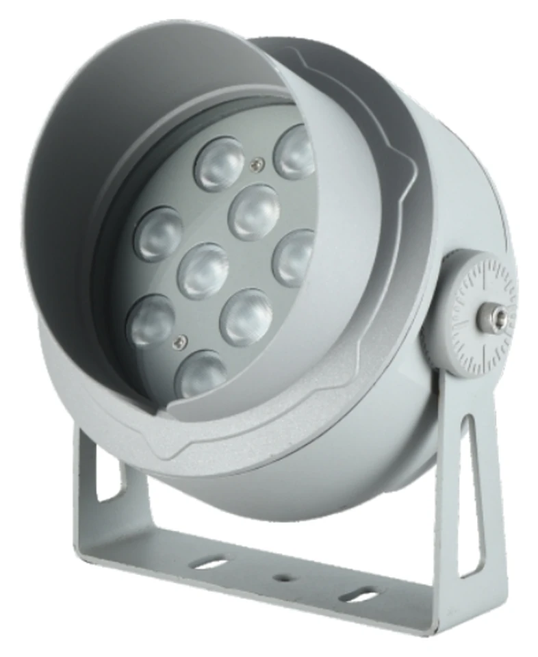
LED Flood Lights
Architectural LED flood lights for facades, landmarks, landscapes and outdoor lighting projects.
Browse Flood Lights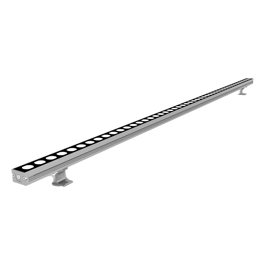
LED Wall Washer Lights
Architectural wall washer lighting for building facades, vertical surfaces and outdoor structures.
Browse Wall Washer Lights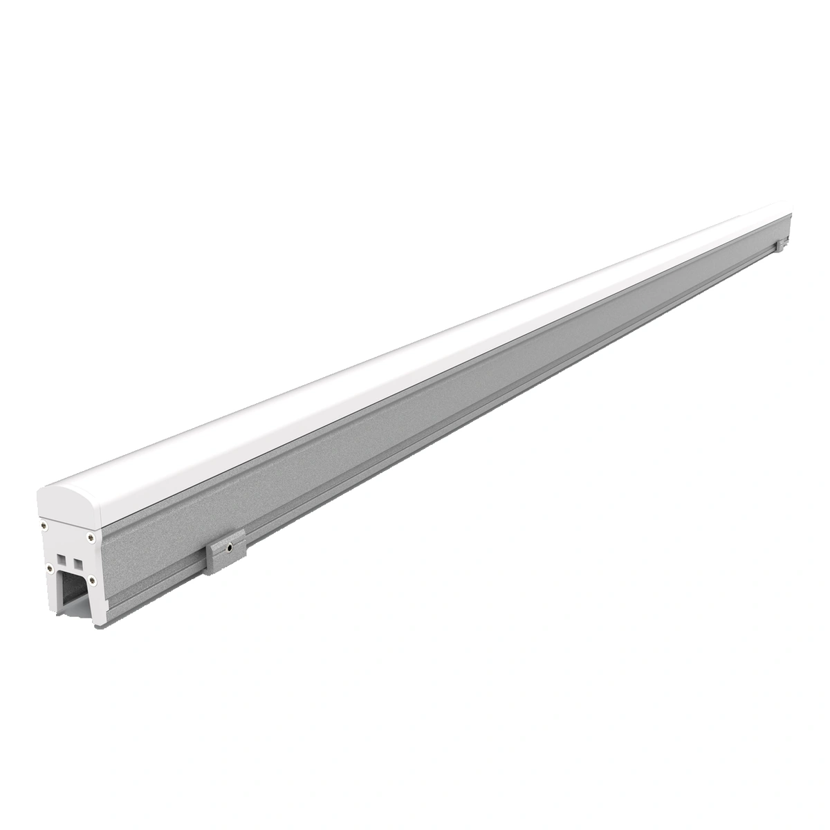
LED Linear Lights
Architectural LED linear lights with model-specific PC covers, glass faces or aluminium aperture-style profiles.
Browse Linear LightsProject Inquiry
Discuss Your Facade Lighting Project
Tell us about your facade, desired lighting effect and project requirements.