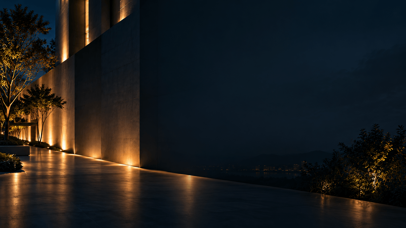
Mounting distance changes where a luminaire’s light reaches the facade; beam angle describes part of how that light is distributed. Neither determines facade lighting uniformity by itself. The installed result also depends on the complete luminous-intensity distribution, aiming orientation, spacing between luminaires, wall geometry, and the surfaces being illuminated. A wider beam or a greater wall offset can improve coverage in one arrangement and create unwanted spill or weak coverage in another.
For project decisions, compare candidate layouts using the same defined facade area and vertical illuminance calculation grid. Then check the visible light pattern from the actual viewing positions. This is more reliable than adopting one mounting ratio for every wall washer.
Beam angle describes a distribution, not an even patch on the wall
A commonly reported beam angle is the angular spread between directions at which luminous intensity falls to half its peak value in a specified plane. It does not mark a hard edge where the light stops. Nor does it describe every part of an asymmetric wallwasher distribution, which may send different amounts of light upward, downward, and sideways.
Two luminaires with the same stated beam angle may therefore produce different vertical brightness patterns. One could concentrate much of its output near the bottom of a facade; another may be designed to push light higher up the wall. For that reason, comparing nominal angles alone is not sufficient for selecting wallwashing optics. Obtain the photometric distribution for the exact optic and luminaire configuration.
How mounting distance changes facade coverage
The wall offset is the horizontal distance from the luminaire’s defined mounting or photometric reference point to the facade. The luminaire spacing is the distance between neighbouring fittings along the wall. The aiming angle describes the installed orientation. These are separate variables, and all three should appear on the installation drawing.
With the same luminaire and an appropriate change of aim, moving a fitting away from the wall often allows its light to reach a broader vertical region at less oblique incidence. But it also changes light-path length, the light distribution over the wall, spill beyond its edges, and the visibility of the source. Moving it closer may produce a stronger grazing effect, greater sensitivity to wall texture, or a bright region near the luminaire. These are tendencies, not guaranteed outcomes; the actual optic can alter them considerably.
The amount of overlap between adjacent luminaires matters as much as individual beam coverage. Two beams may reach the full wall height yet still create a rhythm of bright and dark vertical bands if their distributions do not overlap appropriately.
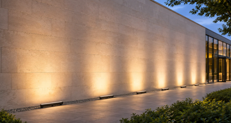
Figure 1. Illustrative facade wall washing with visible light patches between adjacent luminaires. Conceptual visual only; not a CRANE installation, photometric result, or demonstration of measured uniformity.
A smooth-looking photograph cannot replace an illuminance grid. Camera exposure, tone mapping, surface reflectance and the viewer’s adaptation affect apparent brightness. Conversely, a facade with intentionally accented columns or textured masonry should not be judged against the same visual-uniformity goal as a continuous, smooth stone wall.
A repeatable way to compare mounting distance, optics and spacing
Start with a dimensioned elevation and section. Mark the intended illuminated area, its height and width, every mounting constraint, and the main observer positions. Identify openings and other areas that should not be part of the illuminated target. Do not remove inconvenient dark regions from the evaluation after seeing the results.
The following comparison sequence prevents three design variables from being changed at once:
| Test | What to vary | What to keep consistent | What to examine |
|---|---|---|---|
| A — Wall offset | Evaluate feasible near, intermediate and farther positions, without assigning universal distances | Same luminaire/optic, spacing, output and target area; re-aim each candidate to a documented reference target if needed | Upper- and lower-wall coverage, vertical gradient, spill and visible source exposure |
| B — Optical distribution | Compare verified candidate beam distributions at the preferred feasible offset | Same target area, luminaire positions and comparison criteria; use each optic’s documented orientation | Difference between the bright and dim wall regions, lateral spread and unwanted light |
| C — Luminaire spacing | Compare closer and wider spacing using the selected optic and offset | Same optic, nominal output, installation height and target area | Overlap between luminaires, repeated bright bands, darker gaps and fitting count |
Evaluate every layout on an unchanged vertical calculation surface. Record minimum, average and maximum vertical illuminance across a stated grid, with the calculation boundary and grid spacing saved in the report. A useful descriptive index is:
[
U_0 = \frac{E_{v,\min}}{E_{v,\mathrm{avg}}}
]
Here, (E_v) is vertical illuminance in lux, (E_{v,\min}) is the lowest sampled value, and (E_{v,\mathrm{avg}}) is the arithmetic mean of values over the same specified evaluation area. A higher ratio indicates less variation by this particular measure, but it is not proof of a pleasing facade or compliance with a universal outdoor standard. Also inspect the absolute illuminance values, horizontal and vertical profiles, brightness transitions, observer glare and spill. Define acceptable limits for the specific project before choosing the preferred option.
If the candidates have very different average illuminances, compare both the actual operating conditions and, where appropriate, a normalized comparison at a common target average. Keep the scaling assumptions visible. Do not select a layout solely because its uniformity ratio looks favorable while the required wall brightness or light control is inadequate.
Why a beam-width formula cannot finish the design
A simple beam-footprint calculation can describe the geometry of a cone on a plane perpendicular to its central axis. A facade illuminated obliquely is not that case. The shape of the illuminated region is distorted by tilt and wall intersection, and real wallwasher distributions are not necessarily cones with uniform intensity.
Under an ideal far-field, point-source, direct-light approximation, illuminance at a wall point can be expressed as:
[
E_v(P) \approx \sum_j \frac{I_j(\theta_j,\phi_j)\cos\alpha_j}{r_j^2}
]
where (I_j) is luminous intensity toward the point in candela, (r_j) is the source-to-point distance in metres, and (\alpha_j) is the incidence angle relative to the wall’s surface normal. The sum represents contributions from the luminaires considered; the result is in lux under these assumptions. This relation explains why changing distance or aim changes the delivered illuminance even if the nominal beam angle is unchanged. It does not replace a complete calculation for an extended luminaire, reflected light, obstructions or a close-mounted linear wallwasher.
In particular, a long linear fitting used close to the facade can fall within a near-field regime where a conventional far-field point-source representation is insufficient. Check whether the chosen software and photometric data represent the luminous area adequately. If that cannot be established, request suitable supporting data or test the installation at its real offset.
Diagnose uneven wall washing before changing the product
| Observed problem | Possible causes to investigate | Practical next check |
|---|---|---|
| Strong brightness close to the fixture, insufficient light higher up | Offset, tilt or vertical intensity distribution may not suit the wall height | Review vertical illuminance profile and exact optic; compare another feasible offset/aim |
| Alternating bright columns and dark gaps | Longitudinal spacing or sideways beam overlap may be unsuitable | Compare cross-wall profiles at mid-height and near the top; test closer spacing |
| Acceptable average illuminance but distracting bright patches | Local peaks are hidden by the average; wall finish may emphasize them | Review minimum/maximum grid values and surface appearance from design viewpoints |
| Light spilling beyond the facade or into windows | Excessive spread, inappropriate aim, missing shielding, or unsuitable optical orientation | Recheck beam direction, boundary spill and sightlines; consider a different verified distribution |
| Good simulation but poor result on site | Input geometry, mounting position, aiming, surface finish, photometry or close-range model assumptions may differ | Compare as-built positions and product IDs with the model; assess a representative sample |
These symptoms suggest an investigation order, not a one-to-one diagnosis. Changing wattage may change brightness but will not necessarily correct poor beam placement or overlap.
Verify the design on the actual facade
Before approval, request the IES/LDT photometric file and installation instructions for the specified optical configuration. Confirm the photometric orientation, bracket adjustment range and any shielding accessories. Use real mounting coordinates and the stated target area in the calculation model.
For a representative on-site test, document the luminaire models and output settings, exact offsets, spacing, aiming and operating conditions. If quantitative readings are part of acceptance, measure vertical illuminance with a suitable instrument on a pre-agreed wall grid, keeping the detector orientation and measurement conditions consistent. Assess appearance separately from key pedestrian, approach and neighbouring-window viewpoints. Confirm that material texture, windows, corners and environmental light restrictions do not undermine the proposed arrangement.
The approved result should identify a specific luminaire configuration and installation geometry together, not just a beam angle or a distance rule.
Frequently Asked Questions
Can one wall-offset ratio be used for all wall washers?
No. Manufacturer layout ratios apply to particular optical designs and assumptions, such as wall height and mounting orientation. Treat them as a starting point only for the referenced product family, and confirm the project layout with the matching photometry.
If two products have the same beam angle, will they have the same uniformity?
Not necessarily. The full intensity distribution, optical asymmetry, luminous size and orientation can be different. Compare the actual photometric files on the same facade geometry and grid.
Is tighter luminaire spacing always better?
Not automatically. It can reduce dark gaps in some arrangements, but may increase local overlap and average illuminance, cost and unwanted light. Evaluate spacing together with the target levels, optical distribution and visual pattern.
What should be checked on a glass or highly reflective facade?
Do not treat it as an opaque diffuse wall. Reflections, transmission, interior lighting and observation angles can dominate its appearance. Consider whether opaque panels or architectural framing should be the lighting target instead, and verify a sample from relevant viewpoints.
How should an existing installation be improved if the mounting positions cannot move?
Measure or model the existing pattern and verify the installed optic and aim. Compare compatible optical distributions, adjustment ranges, shielding and permissible spacing changes. Do not assume a wider beam or higher output will correct the root cause.
What should a purchaser request before approving a substitution?
Ask for the exact luminaire and optic identification, matching IES/LDT data, mounting and aiming details, any applicable environmental and electrical documents, and a comparison on the project’s target wall and calculation grid. Resolve differences in output and optical orientation before approval.
Discuss your facade lighting layout with CRANE
For an initial discussion with CRANE, share the facade elevation and section, wall finishes, feasible mounting positions, desired visual effect and key viewing locations. Request configuration-specific photometric and installation documents so suitable wall washer options can be evaluated against the same project criteria.

Ethan Lee
Product Selection
Explore Lighting Products for Facade Projects
Compare product families by the lighting effect, mounting position and architectural detail you need to achieve.
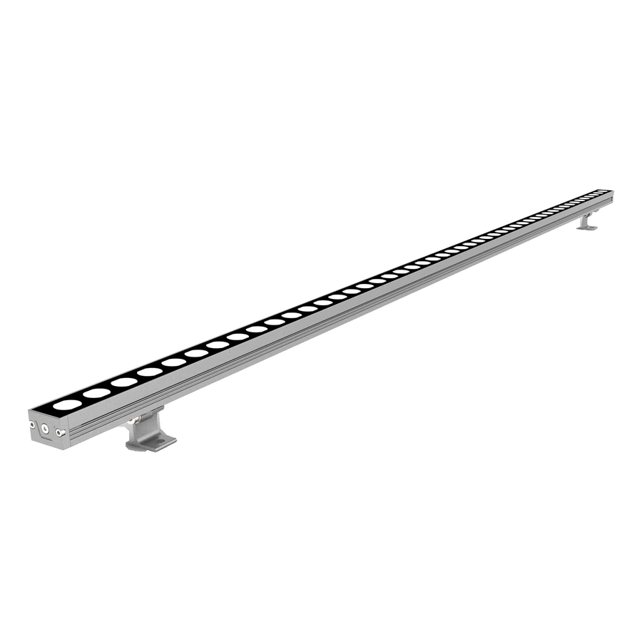
LED Wall Washer Lights
Architectural wall washer lighting for building facades, vertical surfaces and outdoor structures.
Browse Wall Washer Lights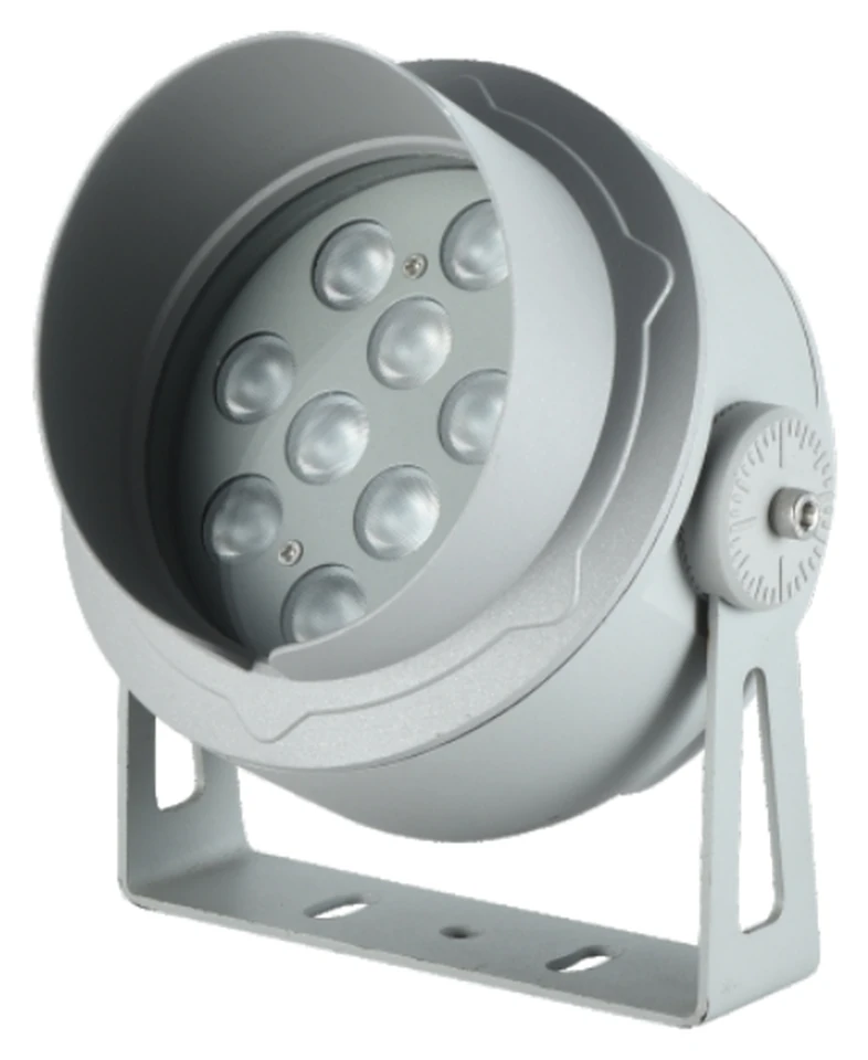
LED Flood Lights
Architectural LED flood lights for facades, landmarks, landscapes and outdoor lighting projects.
Browse Flood Lights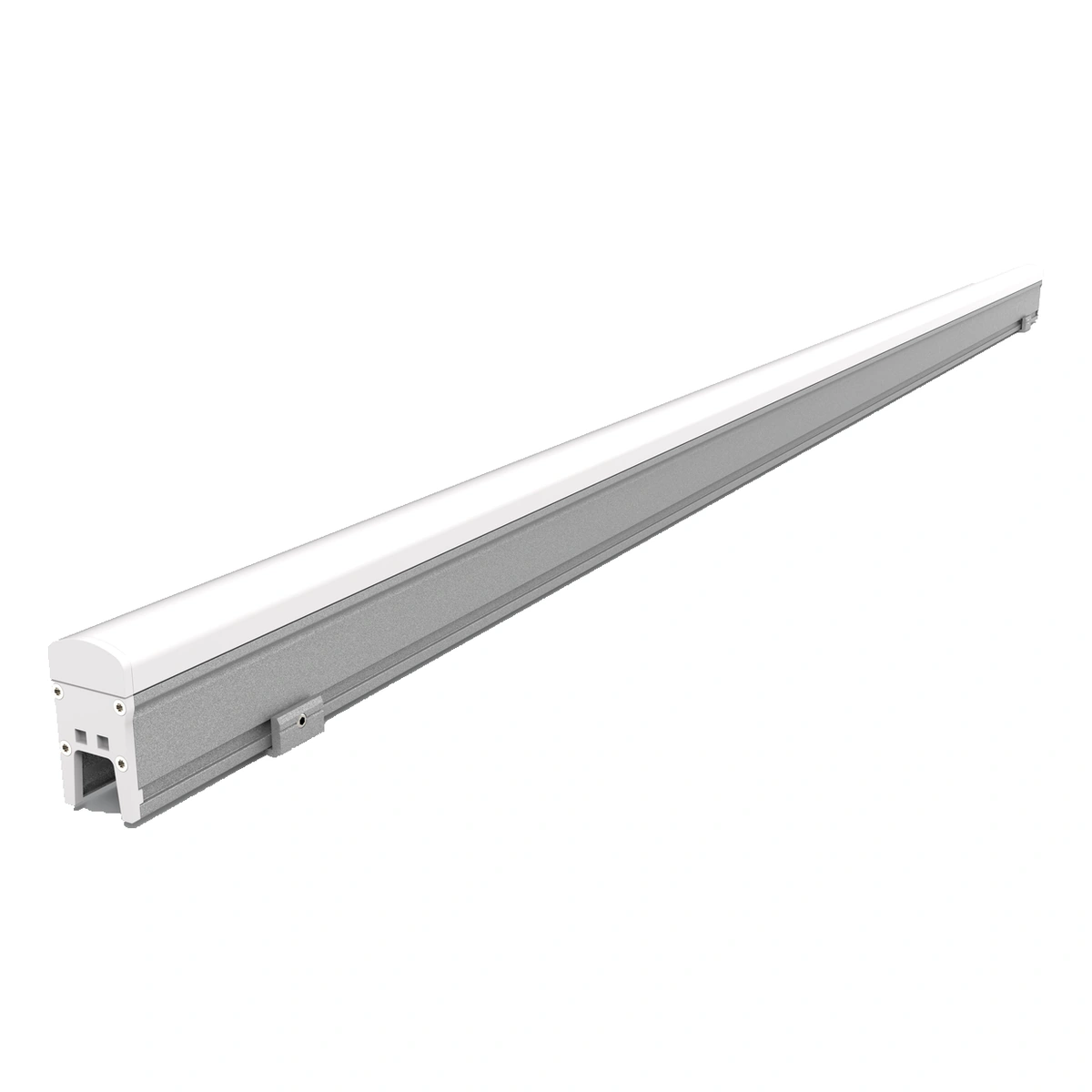
LED Linear Lights
Architectural LED linear lights with model-specific PC covers, glass faces or aluminium aperture-style profiles.
Browse Linear LightsExplore Facade Lighting Solutions
Related Project
See Facade Lighting in Practice
NOVATEK Commercial Complex
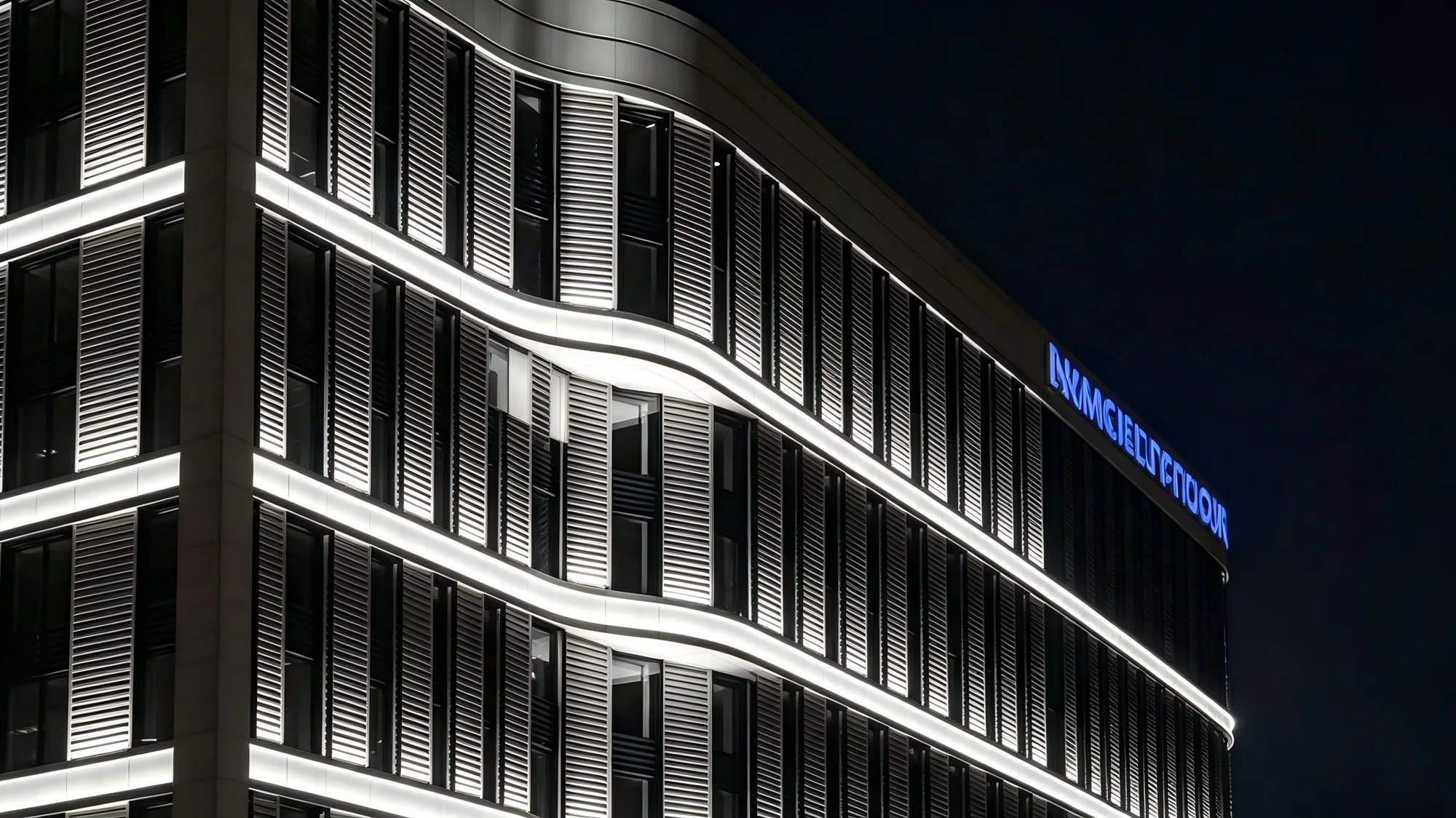
At NOVATEK Commercial Complex in Russia, continuous white lighting follows the building’s horizontal facade lines, turning smoothly around rounded corners. CRANE supplied LED wall washers and custom adjustable mounting brackets for the architectural lighting installation.
View the Lighting ProjectProject Inquiry
Discuss Your Facade Lighting Project
Tell us about your facade, desired lighting effect and project requirements.