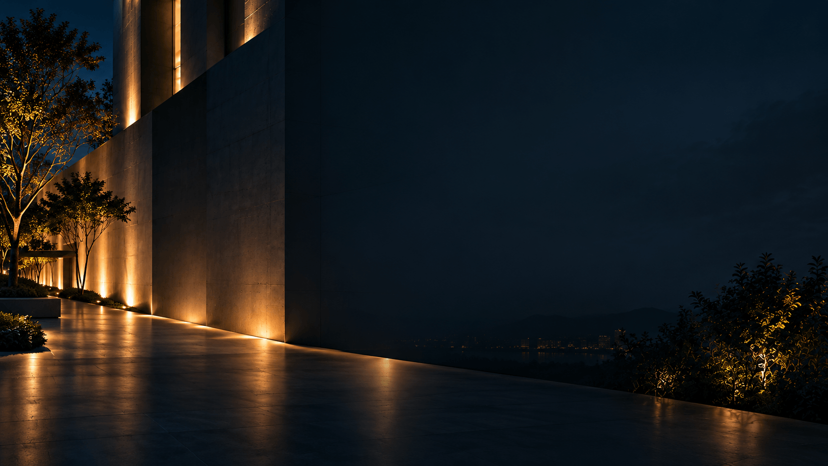
Asymmetric optics are often a strong starting point when a luminaire must direct light along a facade from a constrained mounting position. Symmetric optics remain useful when the fitting can be aimed toward a defined feature or facade zone. Neither distribution guarantees a uniform result. The better choice depends on the required appearance, wall geometry, luminaire position, surface material, viewing directions, and the actual photometric distribution—not the optic label alone.
What changes between symmetric and asymmetric optics?
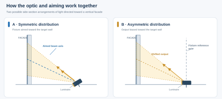
A symmetric optic has a balanced luminous-intensity pattern about its relevant reference axis or plane. It can form a narrow accent beam, a broad flood distribution, or another balanced pattern. Symmetry does not necessarily mean a circular beam: a distribution can have different horizontal and vertical spreads and still be symmetric about its principal planes.
An asymmetric optic deliberately shifts the intensity distribution toward one side of a reference axis or plane. In facade lighting, that shift can help place light on a vertical surface when the luminaire’s mounting position or permitted aiming is restricted. The useful result is not simply a beam that points sideways, but a distribution that places suitable intensity across the intended surface.
A symmetric luminaire can also light a wall effectively when it is aimed and positioned appropriately. Conversely, an asymmetric luminaire can create bright bands, insufficient upper-wall coverage, or stray light if its distribution and geometry are poorly matched.
Choose the optic for the intended facade effect
Begin with what the observer should see, then check what the mounting arrangement makes possible. The following matrix is an initial selection filter, not a substitute for a calculation or mock-up.
| Project condition | Initial optic to evaluate | Main risk to investigate | Evidence needed before approval |
|---|---|---|---|
| Broad, relatively continuous opaque wall; smooth overall appearance required | Purpose-designed asymmetric wallwasher, compared with an appropriately aimed broad distribution | Bright band near luminaires, weak upper-wall coverage, or visible changes between fittings | Candidate photometry, vertical illuminance map, overlap between adjacent luminaires, and night-time viewing check |
| Columns, recesses, entrances, or individual architectural elements | Aimable symmetric spot/flood or an appropriate shaped distribution | Light extending beyond the feature, direct glare, or unwanted emphasis on adjacent surfaces | Beam placement on the real geometry, observer sightlines, shielding and aiming adjustment |
| Strongly textured stone, brick, or relief; shadows are part of the design | Dedicated grazing distribution; check whether its measured optic is symmetric or asymmetric | Excessive shadow length, harsh near-source brightness, and exaggerated imperfections | Texture sample, actual offset, oblique viewing positions, and full-size mock-up |
| Irregular facade with glazing, fins, deep reveals, or changing planes | Separate optical treatments by zone rather than one universal beam | Reflections, blocked beams, uncontrolled spill, or inconsistent appearance | Material schedule, sections, zone-by-zone photometry, and representative on-site tests |
Why mounting geometry can overturn the first choice
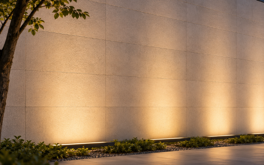
A photometric distribution describes where a luminaire sends light relative to its own orientation. The facade receives that light after the luminaire is positioned and aimed in three-dimensional space. Changing the wall offset, mounting height, tilt or spacing changes the illuminated area and the overlap between fittings—even when the optic itself is unchanged.
For an even wallwash, examine the vertical illumination over the full intended height and across the joints between adjacent beams. A bright base does not demonstrate that the top of the facade is adequately illuminated. For accent lighting, a deliberately non-uniform pattern may be correct, provided the bright and dark areas follow the design intent. For grazing, moving the source close to the surface can strengthen the visibility of joints and protrusions through directional shadows; this is a different goal from suppressing surface texture with a smooth wash.
Avoid transferring a manufacturer’s suggested wall-offset or spacing ratio from one luminaire family to another. Such recommendations depend on the tested optic, target height, aiming geometry and stated design criterion. Treat published arrangement diagrams as product-specific starting points, then verify the proposed installation.
A five-step method to verify the choice
This workflow turns a preliminary optics preference into a checkable design decision.
1. Define the target and acceptance conditions. Record the facade elevation, exact target zones, material finishes, expected viewing positions, permitted mounting points, and whether the goal is an even appearance or intentional accents. Set project-specific criteria for visual consistency, acceptable spill, and glare before comparing fittings. No universal uniformity threshold is assumed here.
2. Compare complete candidate distributions. Request the IES or LDT file for the exact luminaire configuration, together with its photometric report or distribution diagrams. Confirm that the file corresponds to the specified light engine, optic, output, lens or shield, and mounting orientation. A nominal beam angle alone cannot establish where the peak intensity falls or how rapidly intensity declines in different planes.
3. Model the real facade, not a blank rectangle. Include the intended mounting coordinates, aiming angles, reveals, projections, glazing, obstructions, and material reflectance assumptions. Calculate vertical illuminance on the target surfaces; separately review rendered appearance and light leaving the intended facade area. A simulation predicts performance from its input data and assumptions—it does not independently prove that those inputs or the real installation are correct.
4. Check the limits of the model. A conventional far-field photometric file may be less reliable for very short source-to-surface distances, especially where the luminaire is long relative to that distance. Ask whether the software and supplied data adequately represent the luminous geometry. Where they do not, use more suitable data or a physical sample rather than treating the rendering as a measurement.
5. Test from the actual viewing positions. Where the project warrants it, install a representative sample with the proposed brackets and aiming. Inspect the wall from the main approach, pedestrian and nearby-window viewpoints. Compare the intended visual pattern with the mock-up; if quantitative readings are required, define the measurement grid and operating conditions in advance. Record adjustments so the approved setup can be repeated.
Result: Approve the distribution and installation together. If a candidate cannot meet the visual intent without unacceptable spill, glare or mounting compromises, revisit the luminaire or lighting concept—not merely its wattage.
Surface material and spill light are part of the optical decision
An illuminance calculation describes incident light on a surface, not necessarily how bright that surface will appear to a viewer. Surface colour, texture, reflectance, viewing angle and surrounding brightness affect the perceived result. This matters when comparing matte masonry with polished stone, metallic cladding or coated glass.
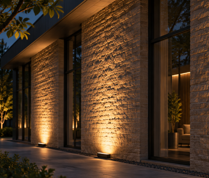
Clear or reflective glazing is especially difficult to treat as an ordinary opaque wall. Depending on the glass and the viewing geometry, substantial light may transmit or produce reflections rather than a stable illuminated facade plane. Consider highlighting mullions, opaque spandrels or architectural framing, or using an interior-lighting strategy if that better matches the design intent. Confirm the selected glass specification and inspect the relevant viewing directions before choosing the approach.
For exterior installations, compare both symmetric and asymmetric candidates for spill beyond the facade and toward neighbouring properties or the sky. Neither classification guarantees good cutoff or low glare. Review the actual installed aim, shielding, intensity distribution and operating schedule, as well as applicable local requirements.
What to request before confirming a luminaire
For an initial technical and purchasing review, supply a dimensioned elevation and section; facade finish or glazing schedule; proposed mounting positions and fixing constraints; the target appearance; key observer locations; control requirements; and any local spill-light restrictions. Ask the supplier to identify the exact candidate luminaire and optical option, provide matching photometric files and installation details, and flag unresolved assumptions.
A project-specific comparison should identify what is confirmed, what depends on mounting or materials, and what needs a sample or revised calculation. It is premature to select a CRANE model from an unverified product listing or infer an available asymmetric optic merely from a product-family name.
Frequently Asked Questions
Can I replace a symmetric floodlight with an asymmetric wallwasher without moving its bracket?
Not on the optic label alone. The replacement may have a different photometric reference direction, required orientation, physical clearance and aiming range. Recalculate the installed arrangement and verify the mounting interface before approving a substitution.
Does an asymmetric optic automatically reduce glare or light pollution?
No. Glare and spill depend on where the light goes after installation, the exposed source, shielding, aiming and observer positions. Evaluate the complete luminaire in the proposed geometry rather than inferring compliance from the word asymmetric.
Can the same optic work on brick and polished stone?
It may, but the visible result can change substantially. Brick joints can form pronounced shadows under directional light; polished surfaces may create distracting reflections. Compare samples under the intended lighting and viewpoints before retaining the same layout.
What if the facade is too close for the available photometric model?
Do not treat a conventional IES/LDT simulation as conclusive. Ask for an appropriate near-field representation or other supporting evidence and check a physical sample at the actual offset, particularly with long linear fittings.
Which files should a contractor request for a tender substitution?
Request the exact luminaire identification, optical option, photometric file, mounting and aiming instructions, overall dimensions, applicable environmental and electrical documentation, and a project comparison showing the target lighting effect. Confirm any ratings and certifications against the proposed configuration and destination market.
Discuss the optical layout for your facade
Share your facade drawings, surface materials, proposed mounting positions and target visual effect with CRANE, and ask for a configuration-specific optics review and the supporting product documents needed to evaluate suitable candidates.

Ethan Lee
Product Selection
Explore Lighting Products for Facade Projects
Compare product families by the lighting effect, mounting position and architectural detail you need to achieve.
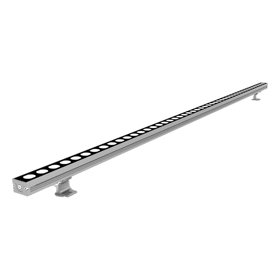
LED Wall Washer Lights
Architectural wall washer lighting for building facades, vertical surfaces and outdoor structures.
Browse Wall Washer Lights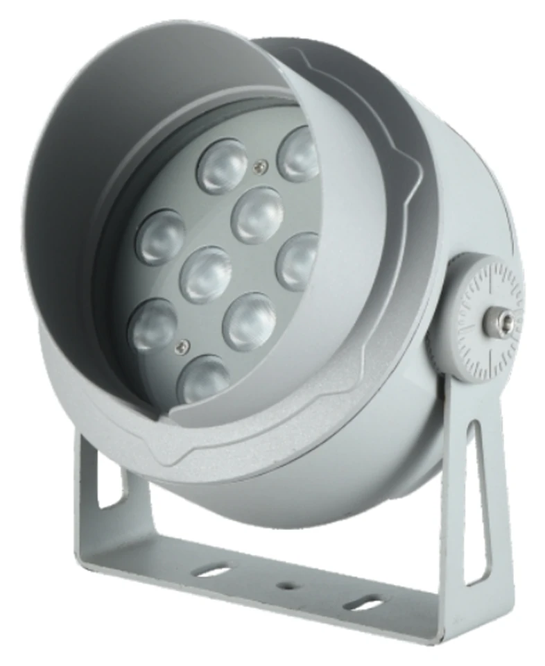
LED Flood Lights
Architectural LED flood lights for facades, landmarks, landscapes and outdoor lighting projects.
Browse Flood Lights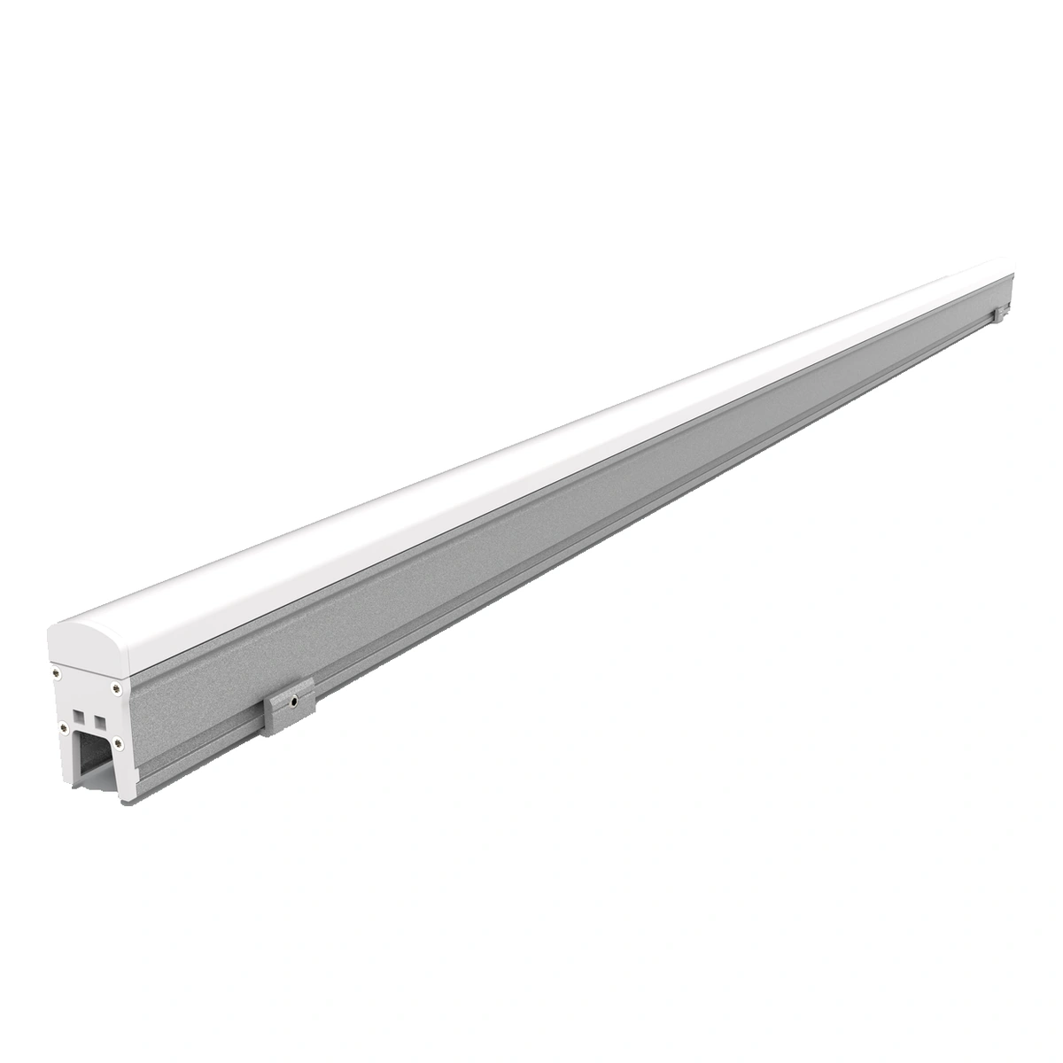
LED Linear Lights
Architectural LED linear lights with model-specific PC covers, glass faces or aluminium aperture-style profiles.
Browse Linear LightsExplore Facade Lighting Solutions
Related Project
See Facade Lighting in Practice
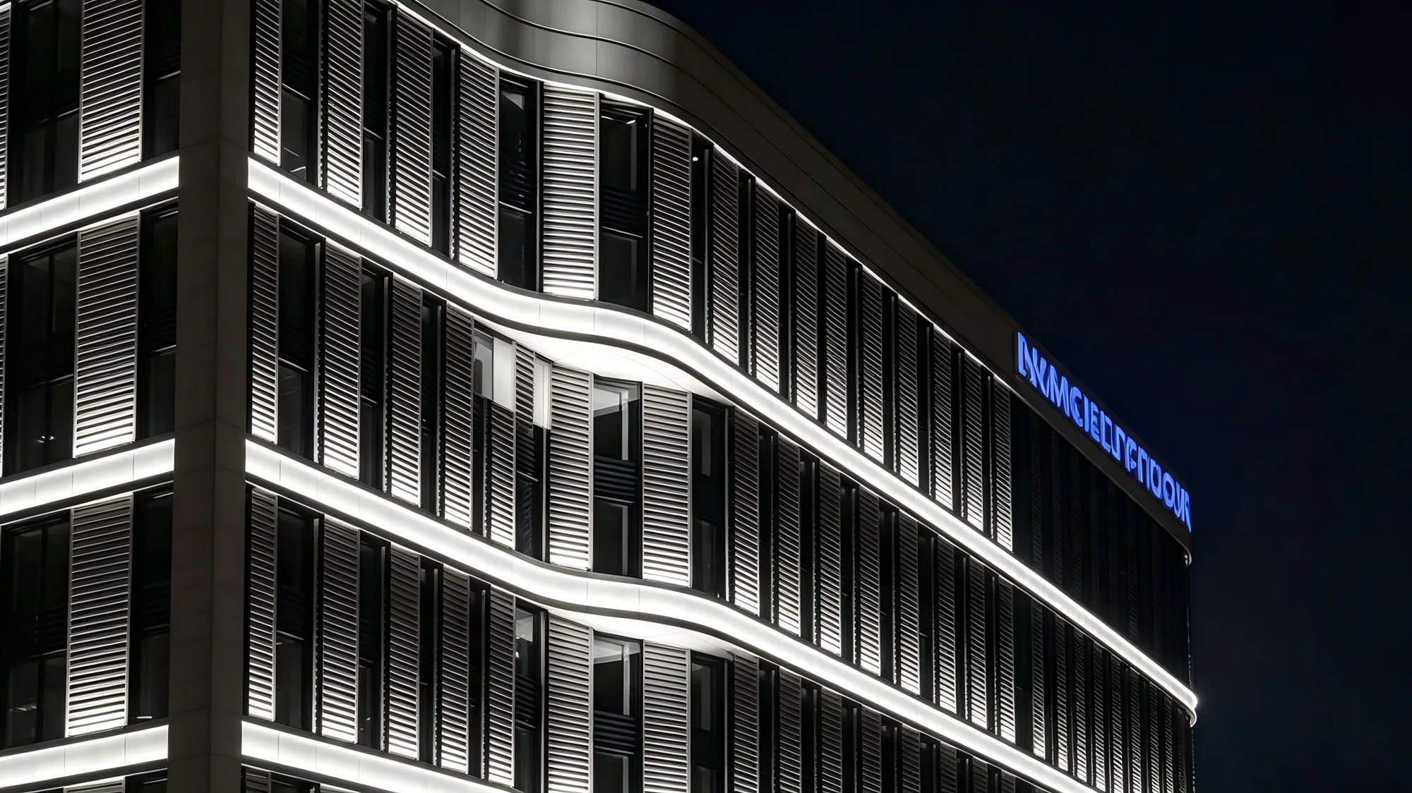
NOVATEK Commercial Complex
At NOVATEK Commercial Complex in Russia, continuous white lighting follows the building’s horizontal facade lines, turning smoothly around rounded corners. CRANE supplied LED wall washers and custom adjustable mounting brackets for the architectural lighting installation.
View the Lighting ProjectProject Inquiry
Discuss Your Facade Lighting Project
Tell us about your facade, desired lighting effect and project requirements.