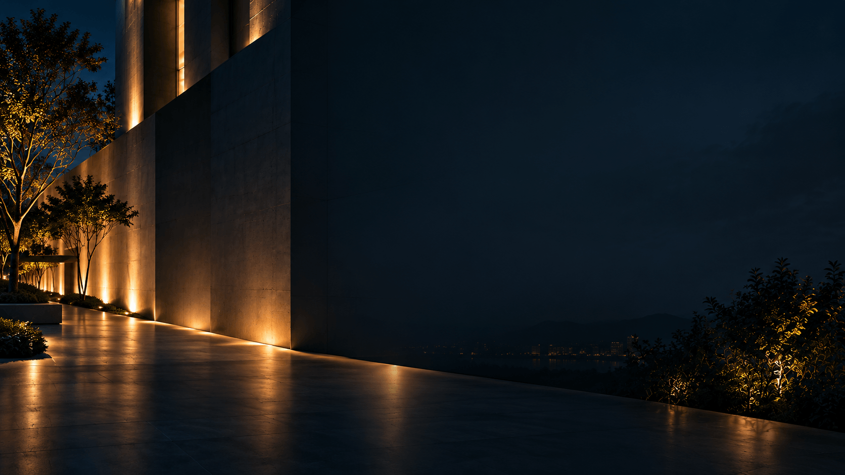
Choose a beam by matching the luminaire’s light distribution to the target’s size, the available mounting position and the desired visual effect. Start with the beam angle to estimate coverage, then check the complete photometric distribution, aiming, spill and viewing conditions. The same nominal angle can produce different results from different luminaires.
For an architectural feature, a relatively concentrated distribution can isolate a detail. For a broad wall, coverage and uniformity may call for a different optic or several overlapping luminaires. Neither choice is reliable until the proposed configuration is assessed against the actual geometry and product data.
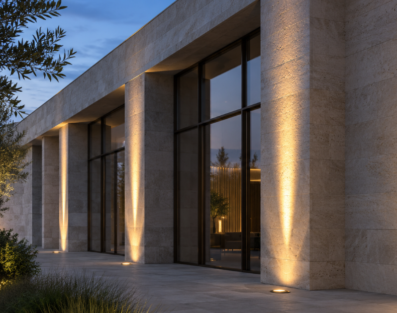
What a beam angle tells you
For a conventional symmetric beam, the stated beam angle commonly describes the angular width between directions where luminous intensity falls to 50% of its maximum. Luminous intensity is expressed in candela (cd) and varies with direction. The angle describes the central part of the distribution; it does not mean that light stops at its boundary.
Some manufacturers also state a field angle, often measured at 10% of maximum intensity. This describes a wider, dimmer portion of the distribution. Definitions and reporting conventions should be checked against the supplier’s photometric information, especially for asymmetric or multi-peaked optics.
Beam angle is not the same as luminous flux in lumens, illuminance in lux, or surface luminance. It does not establish brightness, glare or uniformity on its own. Two fixtures with the same nominal angle can have different peak intensities, edge transitions and spill.
Relate the target to the mounting position
Before choosing an optic, record the visible target, its dimensions, the available fixture locations and the direction from which it will be viewed. Decide whether the aim is to isolate a feature, reveal texture or create a more even illuminated surface.
| Lighting task | Starting point | Decision to verify |
|---|---|---|
| A narrow architectural detail | Consider a concentrated distribution aimed at the feature | Does the complete field remain within acceptable boundaries, and can the mount hold the required aim? |
| A wider sign or facade band | Consider an elongated distribution or multiple luminaires | Are both axes oriented correctly, and is spill onto adjacent windows acceptable? |
| A large vertical wall | Compare a dedicated wall-washing distribution with other proposed optics | Does the predicted and observed coverage meet the project’s uniformity objective? |
| A textured surface | Compare a close, grazing position with a position farther away | Are shadows and surface imperfections consistent with the intended appearance? |
These are selection starting points, not fixed rules. A long throw can favor a concentrated distribution when sufficient intensity is available, but it also makes aiming and obstruction checks more consequential. A wider beam can cover more area at the same distance while sending more light beyond the target.
Estimate the central beam footprint
For an idealized rotationally symmetric beam aimed perpendicular to a flat target, estimate the width of its nominal beam boundary with:
Beam diameter = 2 × throw distance × tan(beam angle ÷ 2)
Use the same length units for the distance and result. The throw is measured from the effective light source to the target along the beam axis; the angle is the full beam angle, not the half-angle.
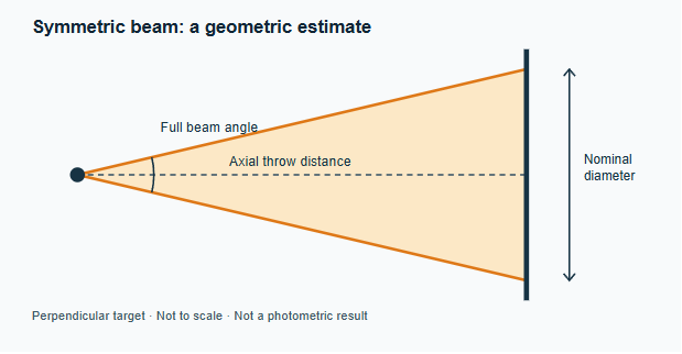
Figure 1. Idealized beam geometry on a plane perpendicular to the beam axis. Conceptual illustration; not a photometric result.*
For a hypothetical 20° symmetric optic with a 3 m axial throw, the calculation gives 2 × 3 × tan(10°), or approximately 1.06 m. This is a geometric estimate of the nominal beam boundary, not the edge of all light or a measurement of illuminance. A wider field can extend beyond it.
If the target is tilted relative to the beam, the footprint becomes distorted; use the actual geometry rather than treating the result as a circle on the facade. The simple formula is not a substitute for a full distribution analysis of an asymmetric, elongated or wall-washing optic.
Compare distributions, not just catalogue angles
Ask for the photometric file corresponding to the exact luminaire, optic, output and accessories under consideration. IES or LDT files can be used in compatible lighting software to examine how intensity varies in different directions and how the selected arrangement illuminates the intended calculation surfaces.
For an elongated beam, check both stated beam dimensions and the orientation of the luminaire. For an asymmetric distribution, identify the intended direction of the high-intensity region and the mounting orientation. A single angle may omit information needed to compare these optics.
Review the calculated illuminance and its variation across the target, together with light falling on adjacent surfaces. Check direct views of the light source from public routes and occupied spaces. Reflections from glass or polished materials require separate attention: an acceptable calculation on the facade does not itself establish comfortable views from every position.
Simulation results depend on the input model, aiming, surface properties and photometric data. Confirm the software settings and data match the design; use a representative physical mock-up where appearance or glare is critical.
A practical selection and verification sequence
- Define the target. Mark the surface to be lit, areas to keep darker and the positions from which the installation will be seen.
- Document the geometry. Record mounting coordinates, available aiming range, obstructions and target dimensions. Identify whether the target is perpendicular to the proposed beam axis.
- Shortlist optics. Use the geometric estimate only for a suitable symmetric beam. For other distributions, use the manufacturer’s distribution and application information.
- Compare real configurations. Request photometry for each proposed optic and accessory combination. Evaluate the same calculation area and aiming assumptions for each option.
- Review trade-offs. Check target coverage, intensity, overlap, spill, direct views and reflections. Reject a configuration that meets the footprint but fails a project requirement elsewhere.
- Validate and document. Where practical, test a representative installation at night from agreed viewing positions. Record the model, optic, mounting position and final aiming settings for procurement and installation.
For example, if a calculated central beam fits a narrow column but field light reaches nearby glazing, changing the aim, location or optic may be more effective than simply reducing the fixture count. Confirm the revised option with the correct photometric file and a site mock-up when needed. This is an illustrative decision, not a recorded CRANE project.
Review a CRANE floodlight candidate
For an architectural feature requiring an adjustable floodlight, the CRANE P Single-Module Architectural LED Floodlights page presents the P Single-Module range and symmetric and elliptical beam options. It can be a candidate for comparison when the required mounting position and target are compatible with the selected configuration.
Before selection, request the current photometric file for the exact model, optic and any accessories, then check aiming range, fixture placement and mounting constraints. Confirm the distribution and output for the proposed configuration; the product page alone does not establish performance on a particular facade.
Frequently asked questions
Does a narrow beam always illuminate a distant surface more effectively?
No. A narrow distribution can concentrate light, but the required result also depends on the fixture’s intensity, target size, aiming and distance. Compare the actual photometric data and check that the target receives the intended coverage.
Can the same optic be used after changing the mounting position?
Possibly, but moving the fixture changes the geometry and may expose different surfaces or viewers to light. Reassess the target coverage and aiming at the new position rather than relying on the original beam-size estimate.
Does a wider beam automatically create a softer edge?
Not necessarily. Edge appearance depends on the optical design and the intensity outside the central beam. Compare field information and, when the edge matters visually, inspect a sample under representative conditions.
Can a diffuser or louvre change the photometric result?
Yes. An accessory can change the emitted distribution and output. Use photometric data for the actual combination where available, and confirm accessory compatibility with the supplier.
How should existing facade lighting be reviewed before a retrofit?
Record the present fixture positions, aiming, visible spill and areas of excessive or insufficient light. Compare those observations with current mounting constraints and the photometry of proposed replacements. Reusing a mounting point does not guarantee the replacement will produce the same effect.
Is an IES or LDT file enough to approve the final appearance?
It is an important input, but it does not replace a review of installation tolerances, finishes, surrounding light and observer positions. For visually sensitive areas, compare the model with a representative mock-up before final approval.

Ethan Lee
Product Selection
Explore Lighting Products for Facade Projects
Compare product families by the lighting effect, mounting position and architectural detail you need to achieve.
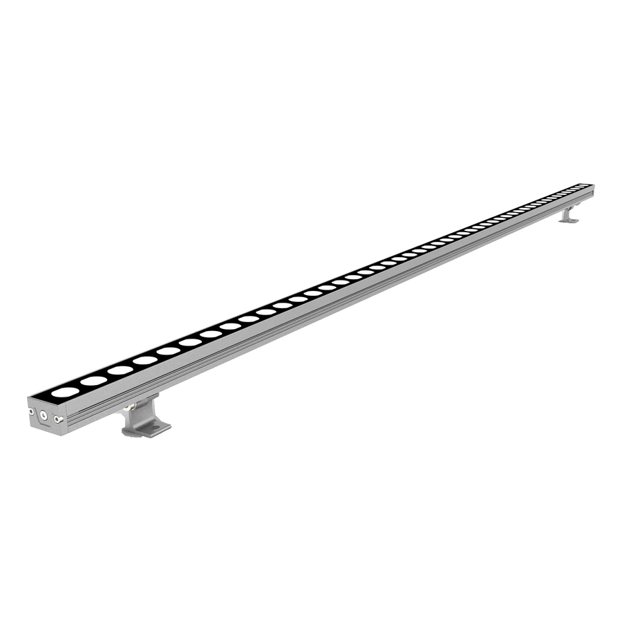
LED Wall Washer Lights
Architectural wall washer lighting for building facades, vertical surfaces and outdoor structures.
Browse Wall Washer Lights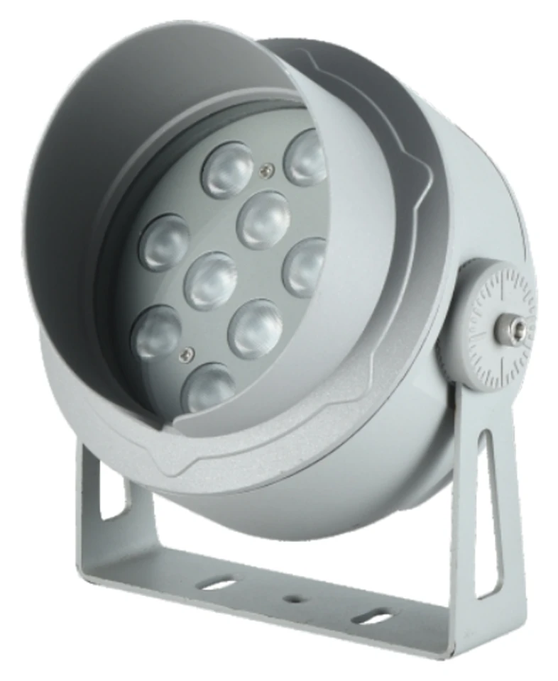
LED Flood Lights
Architectural LED flood lights for facades, landmarks, landscapes and outdoor lighting projects.
Browse Flood Lights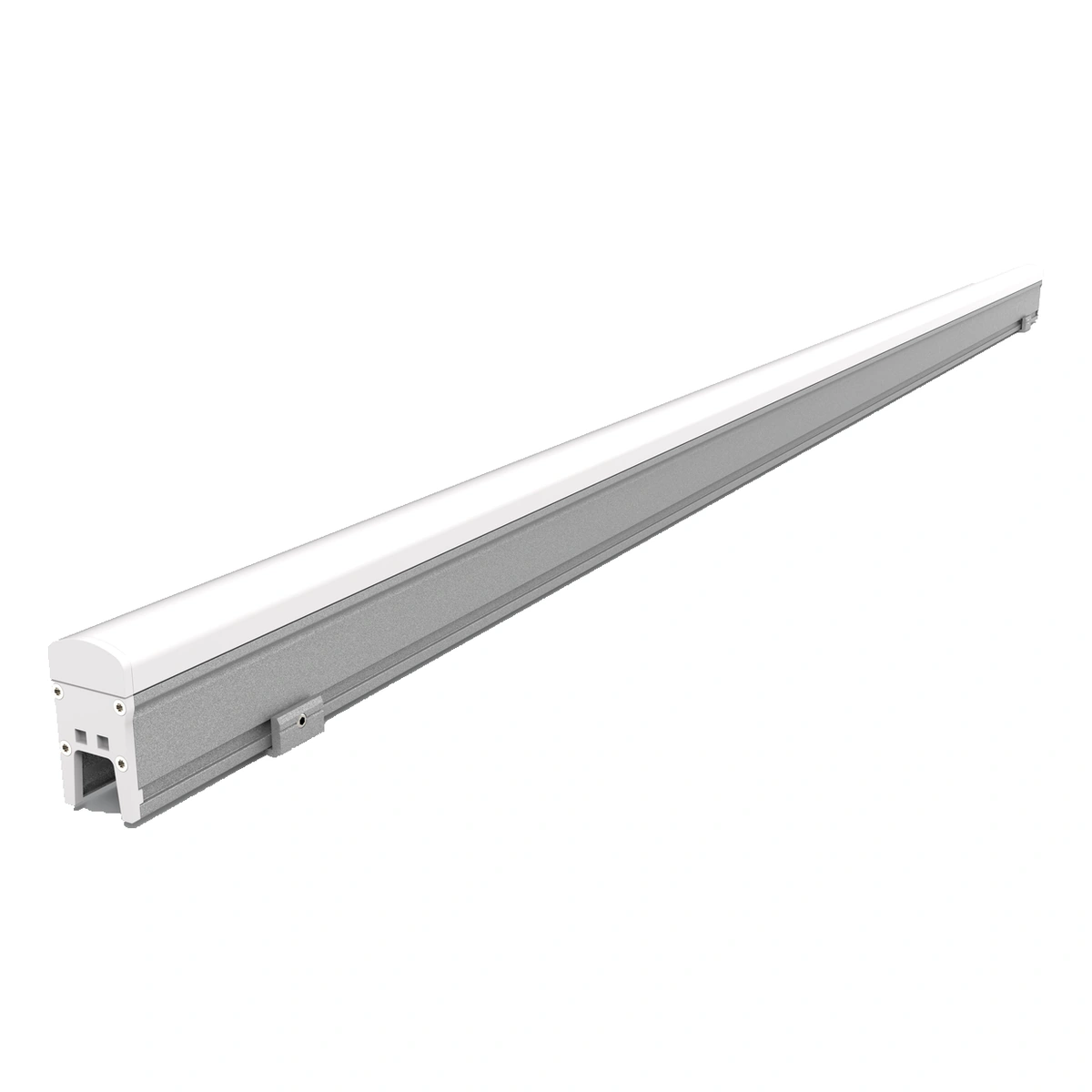
LED Linear Lights
Architectural LED linear lights with model-specific PC covers, glass faces or aluminium aperture-style profiles.
Browse Linear LightsExplore Facade Lighting Solutions
Related Project
See Facade Lighting in Practice
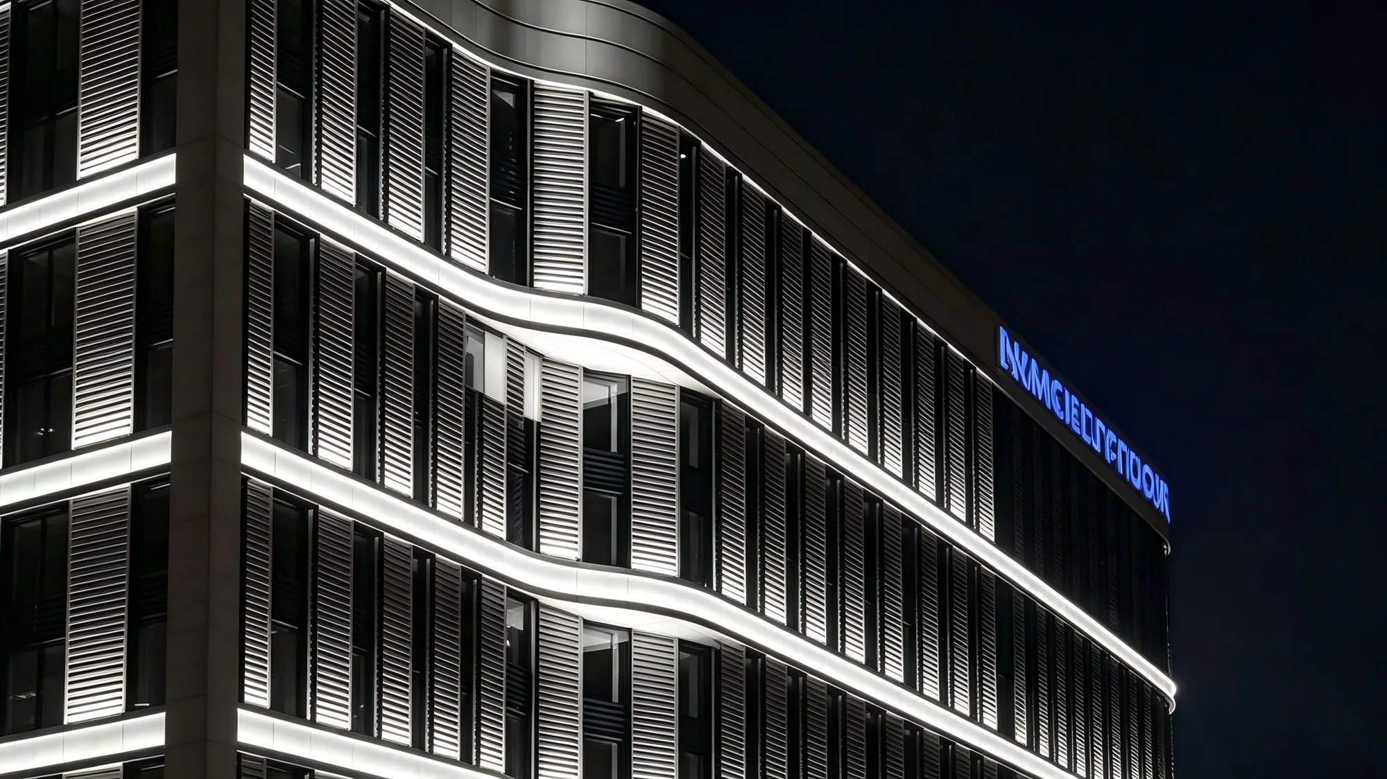
NOVATEK Commercial Complex
At NOVATEK Commercial Complex in Russia, continuous white lighting follows the building’s horizontal facade lines, turning smoothly around rounded corners. CRANE supplied LED wall washers and custom adjustable mounting brackets for the architectural lighting installation.
View the Lighting ProjectProject Inquiry
Discuss Your Facade Lighting Project
Tell us about your facade, desired lighting effect and project requirements.