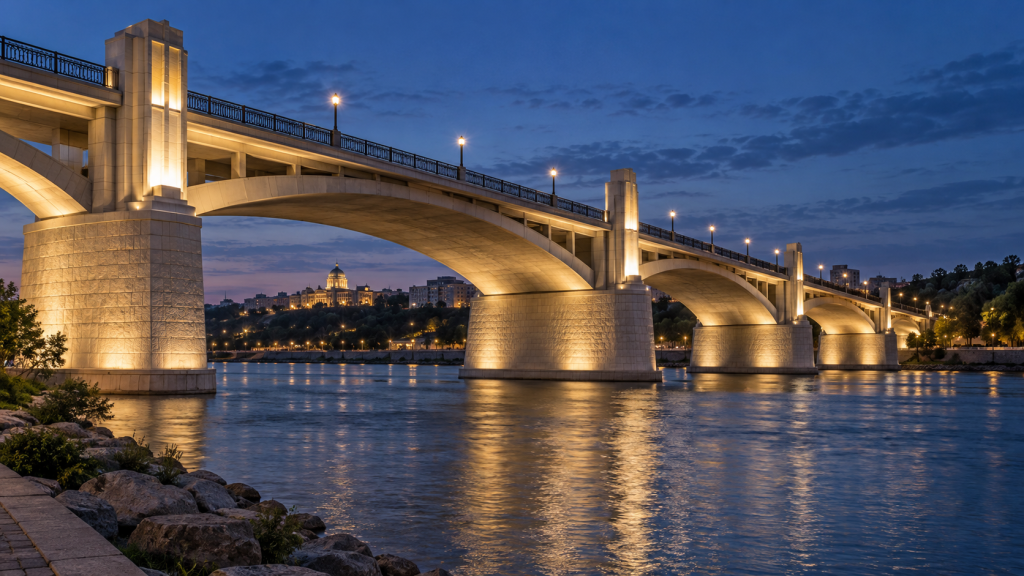
Select LED floodlights by matching the light distribution to the structure and the available mounting positions, then checking glare, spill light and the installed assembly. Wattage alone cannot establish whether a floodlight will illuminate a bridge pylon, reveal a monument or remain suitable on a vibrating structure.
For bridge lighting, separate architectural illumination from road, pedestrian and navigation lighting. A floodlight that makes a structure visible from a distant viewpoint does not, by that fact, meet the requirements of people travelling across or beneath it.
The practical aim is to identify a fixture configuration that can light the intended surfaces, avoid unacceptable effects outside them and be installed and maintained at the proposed location.
Define the target and the viewing conditions before selecting a fixture
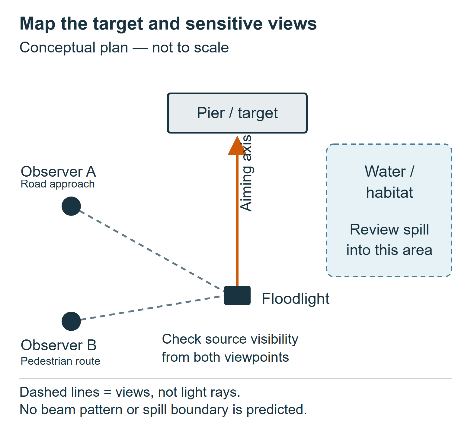
Start with an annotated elevation and a site plan. Mark the surfaces that should be illuminated, the positions where fixtures can actually be mounted and the areas where additional light should be restricted.
“Illuminate the bridge” is too broad a brief. A concrete pier, an open steel truss and a group of suspension cables present different targets. A broad beam may be intercepted by a solid pier but pass through gaps in a truss. Increasing output does not resolve that geometric mismatch.
For landmark lighting, identify the principal viewing distances and directions. A sculpture viewed from several sides may need a different composition from a tower seen mainly from one approach. Do not assume that making every surface equally bright will improve its appearance.
| Project input | What to record | Why it changes the selection |
|---|---|---|
| Target geometry | Width, height, depth, openings and surface orientation | Determines which parts can intercept light from each mounting position |
| Surface finish | Material, colour, gloss and representative samples | Affects apparent brightness and the possibility of reflected glare |
| Mounting geometry | Fixture coordinates, orientation, obstructions and distance to each target | Establishes the required distribution and whether aiming is physically possible |
| Critical viewpoints | Driver approaches, pedestrian routes, nearby windows and waterway views where relevant | Reveals positions from which the source or reflected light could become troublesome |
| Restricted areas | Water, habitat, neighbouring property and open sky, as applicable | Defines where spill must be evaluated and reduced |
| Access and exposure | Maintenance access, structural movement, weather and contaminants | Can rule out an otherwise attractive optical solution |
Match the distribution to the structure, not just its height
The appropriate optic depends on the target’s angular size as seen from the fixture. Two pylons of the same height can require different distributions if one fixture is close to its target and the other is across a river.
Use the following as an initial shortlist, then check it against configuration-specific photometry.
| Target condition | Distribution worth evaluating | Main reason to reject or revise it |
|---|---|---|
| Small, distant architectural feature | Concentrated distribution | Excessive brightness, aiming sensitivity or substantial light missing the feature |
| Long, narrow beam or column | Elongated distribution aligned with the feature | Incorrect orientation, insufficient reach or spill beyond the ends |
| Broad, solid pier or monument face | Wider or asymmetric distribution suited to the mounting position | Bright foreground, dark upper areas or excessive off-target light |
| Open truss or thin cables | Individually targeted lighting, or another lighting approach | Too little of the emitted light is intercepted by the structure |
These are conditional choices, not universal beam-angle recommendations. A narrow optic is useful only if its intensity pattern fits the target and can be aimed and retained accurately. An oval distribution is useful only if its orientation can be matched to the structure using the available fixture and mounting arrangement.
A catalogue beam angle does not describe the complete pattern. Ask for the relevant Illuminating Engineering Society (IES) or EULUMDAT (LDT) photometric file, including the specified optic and any fitted shielding. Do not treat a conceptual beam illustration as measured data.
Compare delivered light rather than watts or total lumens
Wattage describes electrical input. Lumens describe total luminous flux. Neither tells you how much light reaches a particular part of a bridge.
For a distant target, the intensity in the relevant direction matters. Under a point-source approximation, illuminance on a surface perpendicular to an incident ray is proportional to luminous intensity in that direction and inversely proportional to the square of distance. Real assessments must also account for incidence angle, the distribution across the target and obstructions.
Consequently, a higher-lumen fixture with a broad distribution may deliver less light to a small, distant feature than a lower-lumen fixture with a more concentrated distribution. That possibility must be checked using actual data; it is not a reason to assume the narrower product will always perform better.
Also distinguish illuminance from luminance. Illuminance describes light arriving at the surface; luminance describes light leaving it in a particular direction. Equal illuminance does not make dark stone, pale concrete and polished metal appear equally bright. Use representative material properties in calculations and inspect physical samples when appearance is important.
Agree the evaluation areas and required performance with the project team before comparing quotations. A calculation for one favourable point does not demonstrate satisfactory illumination across the target.
Check how sensitive the design is to aiming changes
A distant, narrow target can turn a small aiming change into a substantial shift in the beam axis. This is relevant when comparing mounting locations, bracket adjustment and the ability to restore aiming after maintenance.
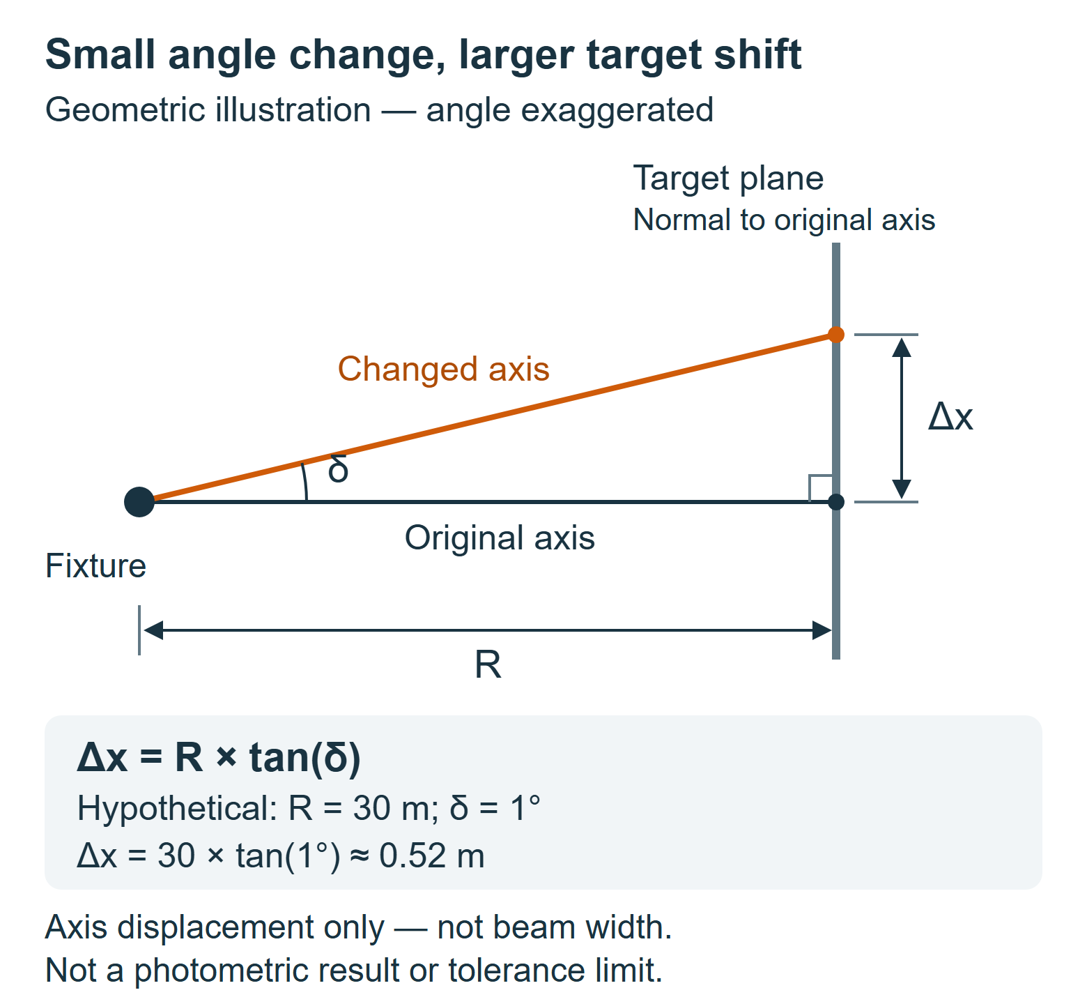
For a simple geometric check, consider a target plane perpendicular to the original aiming axis:
Axis displacement = R × tan(δ)
Here, R is the distance from the fixture’s optical reference point to that plane along the original axis, and δ is an angular change in aiming. The fixture position is assumed to remain fixed.
In a hypothetical example, R = 30 m and δ = 1°:
Axis displacement = 30 × tan(1°) ≈ 0.52 m.
This is an axis displacement, not a beam width, a permitted installation tolerance or a prediction of illuminance. The example does not establish that a fixture will miss its target: that depends on the full distribution, the original aiming point and the target dimensions.
Use this check to identify arrangements that deserve closer evaluation. Compare the calculated shift with the target margins, then assess the actual photometric pattern at the original and changed aiming positions. If the result is too sensitive, investigate a different mounting position, distribution or lighting composition. Simply adding output will not correct an aiming problem.
Review glare and spill from the positions that matter
Assess both the illuminated structure and the visible luminaire. A pleasing view from a riverside promenade can coexist with an objectionable view of the source from a road approach or an apartment window.
For each critical viewpoint, record whether the emitting surface is visible, whether a bright reflection is possible and where unwanted light could travel. Include changes along a route rather than assessing only one stationary observer.
Shielding or louvres may help, but their availability and effect must be verified for the selected product. An accessory can change useful output, clearance and the installed assembly. A narrower optic does not by itself prevent direct glare when someone can see into the source.
Prefer arrangements that intercept light on the intended surfaces. If upward aiming is unavoidable, check overshoot beyond the structure and through openings. Review reflected light as well as direct spill. Where water, wildlife habitat or navigation is involved, establish project-specific constraints with the relevant specialists and responsible authorities rather than applying a generic lux limit.
Set operating hours and dimming scenes around actual need. Evaluate the brightest intended scene as well as the normal scene; an acceptable everyday setting does not validate every programmed event.
Qualify the installed assembly for the site
Treat environmental and mechanical suitability as separate checks from optical suitability. The mounting point may experience conditions that a ground-mounted landscape fixture does not.
Ask for evidence covering the proposed luminaire, bracket, accessories and fixing arrangement, as applicable:
- Structural loading, attachment design and permitted mounting orientations.
- Vibration exposure at the actual mounting location and evidence relevant to the proposed assembly.
- Corrosion protection appropriate to the atmosphere, contaminants and material interfaces.
- Operating temperature, cable entries and the proposed driver location.
- Safe access for cleaning, adjustment and component replacement.
An ingress-protection rating alone does not establish that an assembly can tolerate the site’s vibration or corrosive exposure. Similarly, a test for one bracket arrangement should not automatically be applied to another.
For tender comparison, identify which requirements are demonstrated by submitted documents and which still require review. Keep unresolved mechanical suitability separate from an attractive lighting visualisation: the latter cannot close the former.
Use CRANE product groups as configuration-specific candidates
The following catalogue groups provide two starting points for discussion. Neither recommendation establishes suitability for a particular bridge without the required optical and installation checks.
P Single-Module for larger surface-lighting requirements
The CRANE P Single-Module architectural LED floodlights group lists W380P, W465P and W615P rectangular modules. The W380P catalogue entry gives a configurable power range of 150–200 W.
Consider this group when the brief calls for a substantial surface-lighting fixture and the mounting position can accommodate the selected assembly. The power range is catalogue information, not proof of a particular throw distance or illuminated area.
Provide CRANE with the target dimensions, mounting coordinates, surface information and intended colour configuration. Request the matching photometric file, installation drawing and relevant environmental and mechanical evidence before accepting a specific configuration. Confirm any required glare-control accessory separately.
XY Compact for smaller features and restricted mounting space
The CRANE XY Compact architectural LED floodlights group lists XYLSY-95, XYLSY-150 and XYLSY-180 with compact round housings and U-bracket mounting. The XYLSY-95 catalogue entry lists a configurable power range of 10–15 W.
This group is worth evaluating for a local architectural detail where a smaller assembly is desirable. It should not be assumed to illuminate an entire pylon or a distant landmark merely because it belongs to the floodlight category.
Supply the available mounting envelope and the distance and orientation to the detail. Confirm the installed clearance, adjustment range, cable access and configuration-specific photometry. Bridge-mounted use still requires a separate review of the attachment and site exposure.
Compare quotations against one agreed configuration record
Before ordering, make sure the quotation, drawing, photometry and control description refer to the same configuration. Record:
- Model, optic, output setting and colour version.
- Bracket, orientation and any approved optical accessories.
- Mounting coordinates, aiming points and target surfaces.
- Electrical supply, driver arrangement, control interface and operating scenes.
- Required environmental evidence and maintenance access.
- The calculation and site-review conditions used for acceptance.
For a significant installation, agree a representative nighttime trial and its observation points before committing to the full quantity. Record the tested configuration and settings. Photographs can document the trial, but exposure settings can change apparent brightness; they do not replace appropriate measurements and direct observation.
Frequently asked questions
Can existing floodlight circuits be reused in an LED retrofit?
Do not decide from the lower nominal wattage alone. Ask the electrical designer to review the proposed drivers, starting behaviour, protection, wiring condition and control arrangement against the existing installation. Include the exact driver configuration in the review rather than treating all LED replacements as electrically equivalent.
Does wireless DMX remove the need for power cables?
No. Wireless Digital Multiplex (DMX) carries control information; the luminaires still need a suitable power supply. Confirm compatible transmitters and receivers, test the communication path at the site and define what the fixtures should do if the control signal is lost. A catalogue wireless option does not establish reliable coverage across a particular bridge.
Will different RGBW floodlights produce matching colours from the same control values?
Not necessarily. Red, green, blue and white (RGBW) fixtures do not necessarily produce matching emitted colour from matching control values across different products or configurations. For a coordinated landmark scheme, compare physical samples using the intended scenes and dimming levels, and confirm what adjustment or calibration is available before combining product groups.
How should floodlights be specified for a protected historic structure?
Establish the permitted attachment methods and visual impact with the owner and conservation team before finalising fixtures. A lighting requirement does not itself justify drilling or clamping to historic fabric. If attachments are restricted, assess suitable independent mounting positions and revisit the optical design from those positions.
Can a standard weatherproof floodlight be installed where flooding is possible?
Do not assume a general outdoor designation covers immersion. Identify the possible water exposure, including depth and duration, and obtain explicit suitability information for the complete installation. Where that evidence is unavailable, reconsider the mounting location rather than relying on a general weatherproof claim.
Is the highest-output configuration the best choice for future flexibility?
Only if its usable dimming range and installed size, electrical requirements and maintenance implications suit the project. An oversized fixture can introduce compromises even when dimmed. Define the likely future use and compare suitable configurations instead of purchasing unspecified spare output.
Discuss a project configuration with CRANE
Share the bridge or landmark drawings, proposed mounting positions, target surfaces, critical viewpoints and operating requirements with CRANE. These inputs provide a practical basis for discussing candidate floodlight configurations and identifying the documents needed for project review.

Ethan Lee
Product Selection
Explore Lighting Products for Bridge Projects
Compare product families by the lighting effect, mounting position and architectural detail you need to achieve.
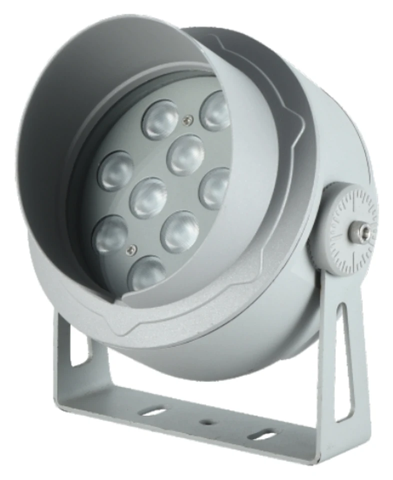
LED Flood Lights
Architectural LED flood lights for facades, landmarks, landscapes and outdoor lighting projects.
Browse Flood Lights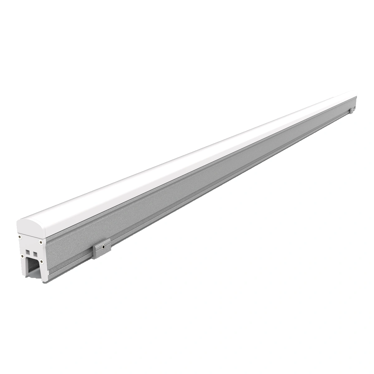
LED Linear Lights
Architectural LED linear lights with model-specific PC covers, glass faces or aluminium aperture-style profiles.
Browse Linear Lights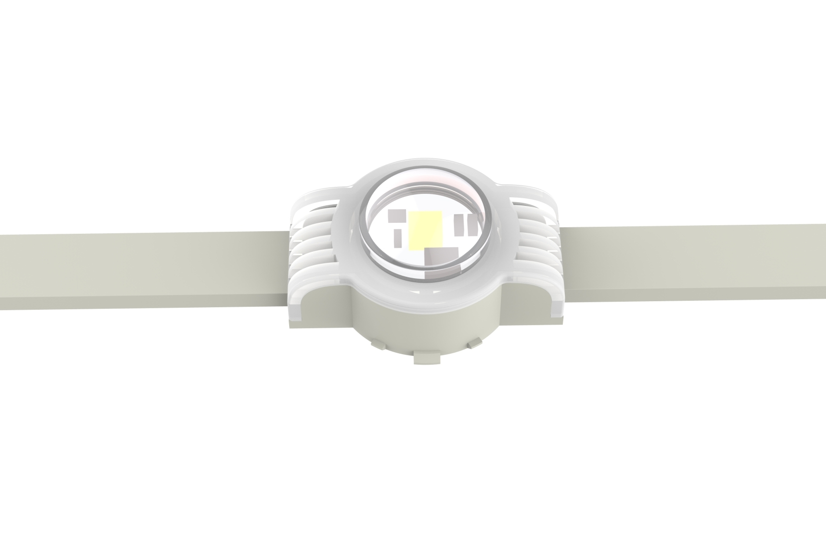
LED Pixel / Point Lights
Compare round YY, square FD and rectangular CH LED point lights for architectural pixel lighting. Select the shape and model, then review supply, mounting, pixel layout and control requirements.
Browse Pixel / Point LightsExplore Bridge Lighting Solutions
Related Project
See Bridge Lighting in Practice
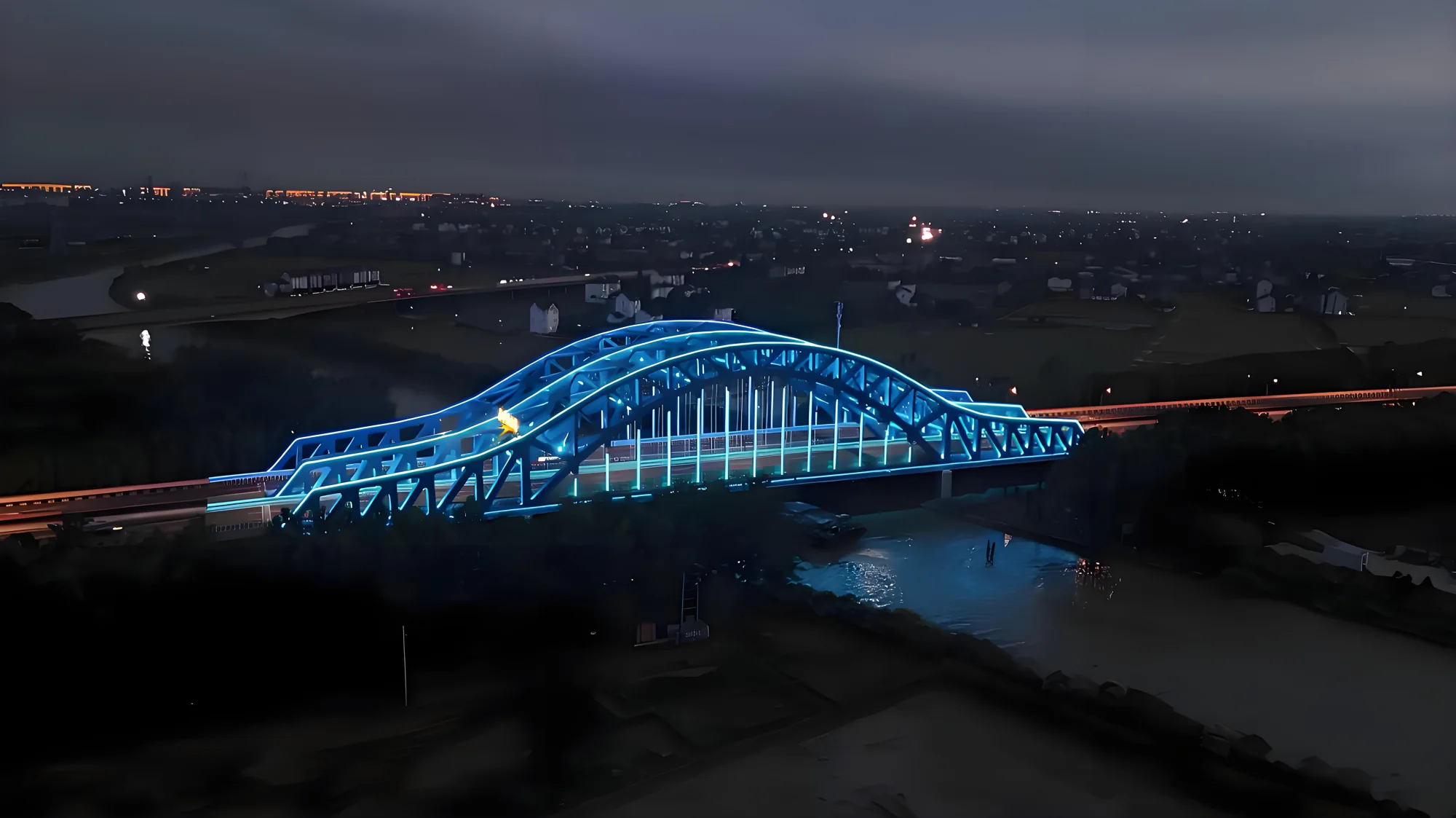
Yanpingtang Bridge
At Yanpingtang Bridge in Jiaxing, RGBW floodlighting reveals the steel arches while linear LEDs trace the intersecting trusswork. CRANE provided lighting design and product supply, with DMX512-controlled scenes for regular evenings and special events.
View the Lighting ProjectProject Inquiry
Discuss Your Facade Lighting Project
Tell us about your facade, desired lighting effect and project requirements.